Installation Instructions
Table of Contents
Important Safety Information
LP-GAS Warning Odor
Safety Information for Users of LP-GAS
Introduction
Fireplace Dimensions Model DVS-30/DVS-36/DVS-42
Specifications
Heater Baffle is Used on DVS-36 & DVS-42 only
Fireplace Component Installation
Clearances Figure
Mantel Chart Figure
Clearances
Locating Fireplace
Checking Manifold Pressures
Installing a New Main Gas Cock
GAS Supply
Example B
Installation
Venting Fireplace
Example a
Vent Runs Figures 14, 15, 16, 17
Three 3 basic types of installations
Framing Figure
Finishing Figure
Installation
Vertical Sidewall Application
Positioning the Fireplace
Cutting the Hole Figures 22
MAX
Information on Various Venting Routes and Components
Vertical Sidewall Installations
Termination Clearances
Vent Clearances
Inner flue joints do not require any sealant
Installing Vent Components Figure
Vent System Identification
DVS-30 Framing and Finishing
Installing Support Brackets Figure
Installing Firestops Figures 30, 31, 32
DVS-30 Framing and Finishing
DVS-36 & DVS-42 Framing and Finishing
Installing Firestops Figures 35, 36, 37
DVS-36 & DVS-42 Framing and Finishing
Vertical Termination For All Models
Installing the Vent System in a Chase
Glass Removal
LOG Placement
Reassembly and Resealing Vent Pipe System
Vertical Through the Roof Applications Figure
TOP View of LOG SET
Glass Replacement
DVS-30 Placement of glowing embers
DVS-36 and DVS-42 Placement of glowing embers
Millivolt System Figures 48
Standing Pilot Operating Instructions
Flame Appearance
Recommended Wire Gauges
Standing Pilot Wiring Diagram
What to do if YOU Smell GAS
Standing Pilot Lighting Instructions
Glass soots
Standing Pilot Troubleshooting
Frequent pilot outage problem
Pilot and main burner extinguish while in operation
Electrical Connection Figure
DVS-36 & DVS-42 Intermittent Pilot Wiring Diagram
To Turn OFF GAS to Appliance
Checkout
Specifications
Operation
Trial for Ignition
Main Burner Operation
Safety Lockout
ARC Length Action
Ignition System Checks
DVS-36 & DVS-42 Intermittent Pilot Troubleshooting
RF Standing Pilot Operating Instructions
RF Wiring Diagram
RF Standing Pilot Lighting Instructions
Please Note
Maintenance and Service
DVS-30 Parts List
HOW to Order Repair Parts
#41 Orifice NAT
DVS-36 Parts List
DVS-42 Parts List
Parts View
Louvers
Accessory Parts
Variable Speed Blower Installation Instructions
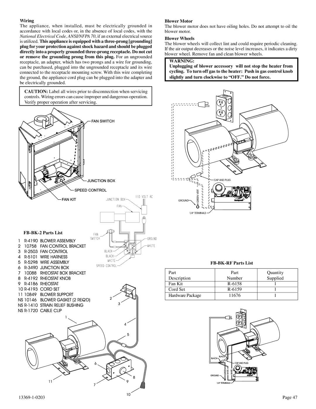
Blower Motor
FBB1A Blower Installation
Optional Single Speed Blower Installation Instructions
Parts List
Optional Fresh Air Intake Kit Figure
Optional Fresh AIR Intake KIT DVFB-AK-30, FB-AK-2
Example of Installation
DVS-BL-30-2, DVS- BL-36-2, DVS-BL-42-2
Installing Optional Brick Liner
Parts List
Brick Liner KIT