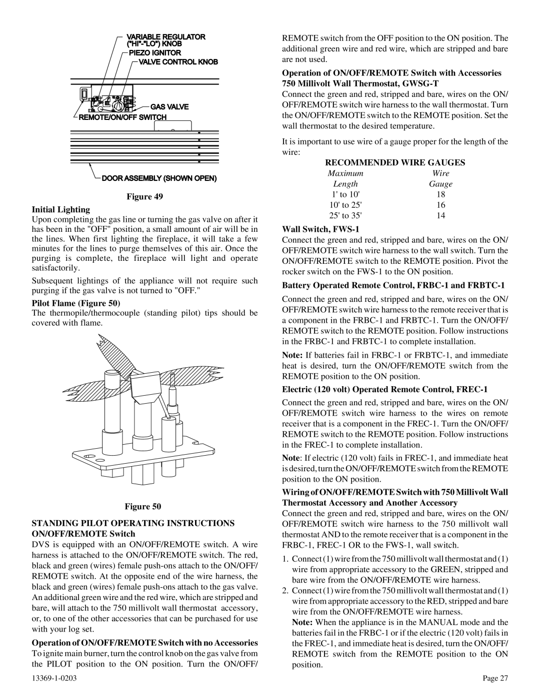
VARIABLE REGULATOR
PIEZO IGNITOR
VALVE CONTROL KNOB
![]()
![]() GAS VALVE
GAS VALVE
REMOTE/ON/OFF SWITCH
DOOR ASSEMBLY (SHOWN OPEN)
Figure 49
Initial Lighting
Upon completing the gas line or turning the gas valve on after it has been in the "OFF" position, a small amount of air will be in the lines. When first lighting the fireplace, it will take a few minutes for the lines to purge themselves of this air. Once the purging is complete, the fireplace will light and operate satisfactorily.
Subsequent lightings of the appliance will not require such purging if the gas valve is not turned to "OFF."
Pilot Flame (Figure 50)
The thermopile/thermocouple (standing pilot) tips should be covered with flame.
Figure 50
STANDING PILOT OPERATING INSTRUCTIONS ON/OFF/REMOTE Switch
DVS is equipped with an ON/OFF/REMOTE switch. A wire harness is attached to the ON/OFF/REMOTE switch. The red, black and green (wires) female
Operation of ON/OFF/REMOTE Switch with no Accessories
To ignite main burner, turn the control knob on the gas valve from the PILOT position to the ON position. Turn the ON/OFF/
REMOTE switch from the OFF position to the ON position. The additional green wire and red wire, which are stripped and bare are not used.
Operation of ON/OFF/REMOTE Switch with Accessories 750 Millivolt Wall Thermostat,
Connect the green and red, stripped and bare, wires on the ON/ OFF/REMOTE switch wire harness to the wall thermostat. Turn the ON/OFF/REMOTE switch to the REMOTE position. Set the wall thermostat to the desired temperature.
It is important to use wire of a gauge proper for the length of the wire:
RECOMMENDED WIRE GAUGES
Maximum | Wire |
Length | Gauge |
1' to 10' | 18 |
10' to 25' | 16 |
25' to 35' | 14 |
Wall Switch, FWS-1
Connect the green and red, stripped and bare, wires on the ON/ OFF/REMOTE switch wire harness to the wall switch. Turn the ON/OFF/REMOTE switch to the REMOTE position. Pivot the rocker switch on the
Battery Operated Remote Control, FRBC-1 and FRBTC-1
Connect the green and red, stripped and bare, wires on the ON/ OFF/REMOTE switch wire harness to the remote receiver that is
acomponent in the
Note: If batteries fail in
Electric (120 volt) Operated Remote Control, FREC-1
Connect the green and red, stripped and bare, wires on the ON/ OFF/REMOTE switch wire harness to the wires on remote receiver that is a component in the
Note: If electric (120 volt) fails in
Wiring of ON/OFF/REMOTE Switch with 750 Millivolt Wall Thermostat Accessory and Another Accessory
Connect the green and red, stripped and bare, wires on the ON/ OFF/REMOTE switch wire harness to the 750 millivolt wall thermostat AND to the remote receiver that is a component in the
1.Connect (1) wire from the 750 millivolt wall thermostat and (1) wire from appropriate accessory to the GREEN, stripped and bare wire from the ON/OFF/REMOTE wire harness.
2.Connect (1) wire from the 750 millivolt wall thermostat and (1) wire from appropriate accessory to the RED, stripped and bare wire from the ON/OFF/REMOTE wire harness.
Note: When the appliance is in the MANUAL mode and the batteries fail in the
Page 27 |