OPTIONAL FRESH AIR INTAKE INSTALLATION INSTRUCTIONS
OPTIONAL FRESH AIR INTAKE KIT
DVFB-AK-30, FB-AK-2
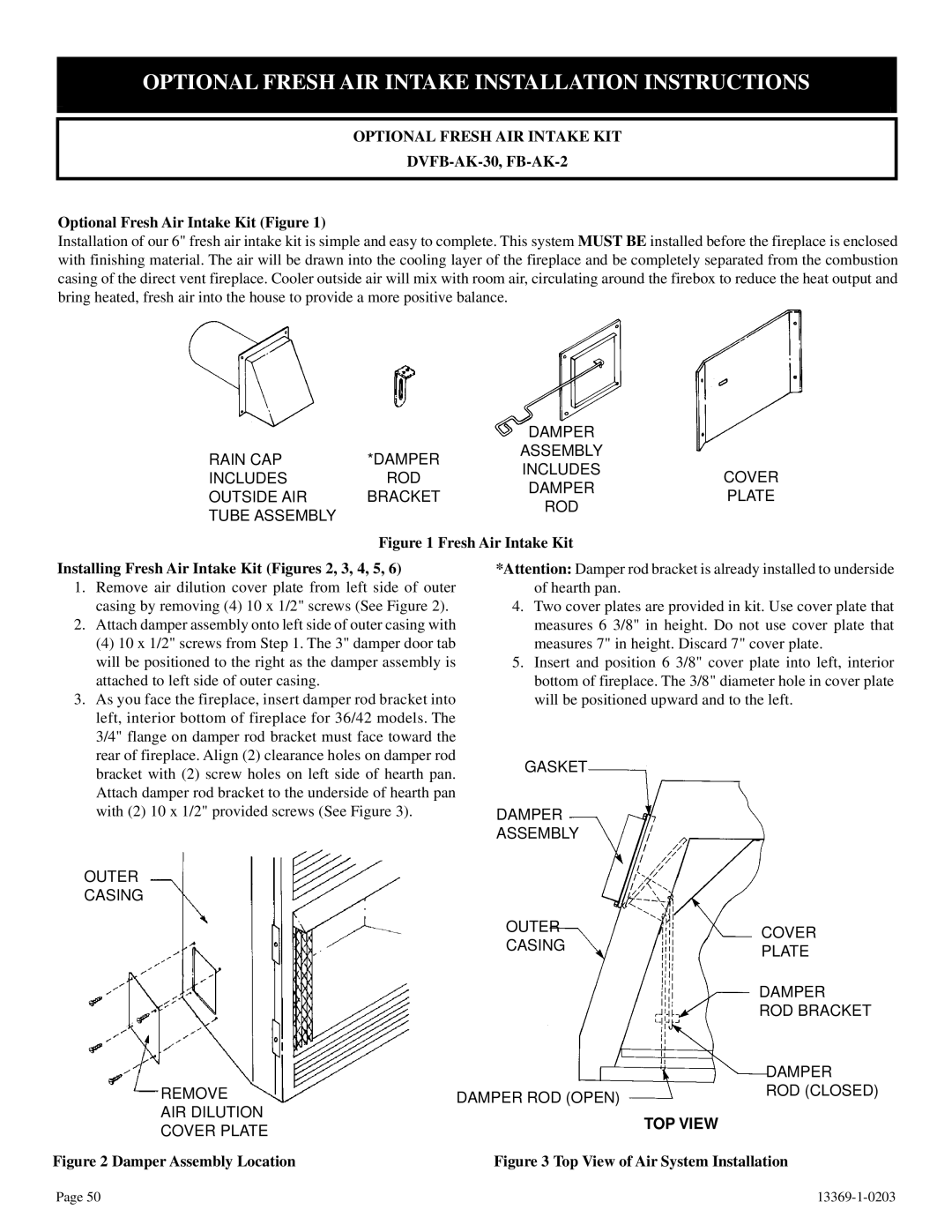
Optional Fresh Air Intake Kit (Figure 1)
Installation of our 6" fresh air intake kit is simple and easy to complete. This system MUST BE installed before the fireplace is enclosed with finishing material. The air will be drawn into the cooling layer of the fireplace and be completely separated from the combustion casing of the direct vent fireplace. Cooler outside air will mix with room air, circulating around the firebox to reduce the heat output and bring heated, fresh air into the house to provide a more positive balance.
|
| DAMPER |
| |
RAIN CAP | *DAMPER | ASSEMBLY |
| |
INCLUDES | COVER | |||
INCLUDES | ROD | |||
DAMPER | ||||
OUTSIDE AIR | BRACKET | PLATE | ||
ROD | ||||
TUBE ASSEMBLY |
|
| ||
|
|
| ||
| Figure 1 Fresh Air Intake Kit |
| ||
Installing Fresh Air Intake Kit (Figures 2, 3, 4, 5, 6) | *Attention: Damper rod bracket is already installed to underside | |||
1. Remove air dilution cover plate from left side of outer | of hearth pan. |
| ||
casing by removing (4) 10 x 1/2" screws (See Figure 2). | 4. Two cover plates are provided in kit. Use cover plate that | |||
2. Attach damper assembly onto left side of outer casing with | measures 6 3/8" in height. Do not use cover plate that | |||
(4) 10 x 1/2" screws from Step 1. The 3" damper door tab | measures 7" in height. Discard 7" cover plate. | |||
will be positioned to the right as the damper assembly is | 5. Insert and position 6 3/8" cover plate into left, interior | |||
attached to left side of outer casing. |
| bottom of fireplace. The 3/8" diameter hole in cover plate | ||
3. As you face the fireplace, insert damper rod bracket into | will be positioned upward and to the left. | |||
left, interior bottom of fireplace for 36/42 models. The |
|
| ||
3/4" flange on damper rod bracket must face toward the |
|
| ||
rear of fireplace. Align (2) clearance holes on damper rod | GASKET |
| ||
bracket with (2) screw holes on left side of hearth pan. |
| |||
|
| |||
Attach damper rod bracket to the underside of hearth pan |
|
| ||
with (2) 10 x 1/2" provided screws (See Figure 3). | DAMPER |
| ||
|
| ASSEMBLY |
| |
OUTER |
|
|
| |
CASING |
|
|
| |
|
| OUTER | COVER | |
|
| CASING | ||
|
| PLATE | ||
|
|
| ||
|
|
| DAMPER | |
|
|
| ROD BRACKET | |
|
|
| DAMPER | |
REMOVE |
| DAMPER ROD (OPEN) | ROD (CLOSED) | |
AIR DILUTION |
|
| TOP VIEW | |
COVER PLATE |
|
| ||
|
|
| ||
Figure 2 Damper Assembly Location |
| Figure 3 Top View of Air System Installation | ||
Page 50 |