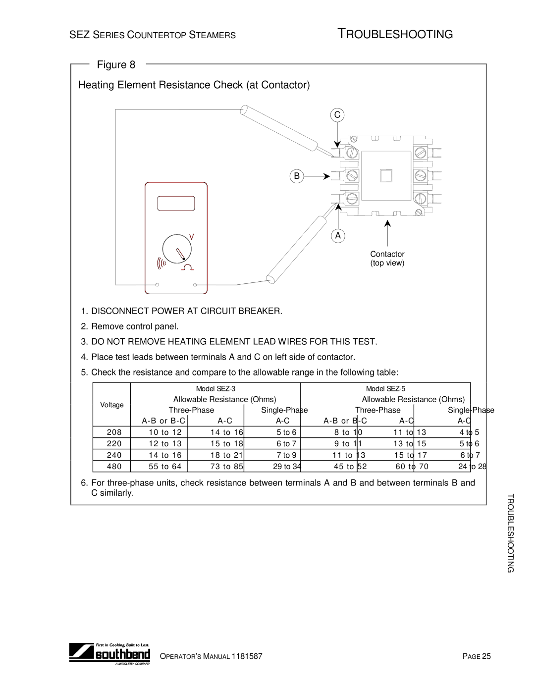
SEZ-3, SEZ-5 specifications
The Southbend SEZ-5 and SEZ-3 are prominent models from Southbend's line of commercial cooking equipment, renowned for their robust construction and high-performance capabilities. These ranges are designed to meet the demands of busy kitchens, such as those found in restaurants, hotels, and catering companies, providing chefs with reliable tools to prepare meals efficiently.One of the main features of the SEZ-5 is its versatile cooking options. It typically includes a combination of open burners, griddles, and ovens, allowing chefs to execute a wide range of cooking techniques. The SEZ-3, while slightly smaller, offers similar functionality tailored for establishments with space constraints but still requiring high output. Both models are equipped with intuitive controls, enabling precise temperature adjustments to ensure optimal cooking conditions.
The construction of both the SEZ-5 and SEZ-3 is noteworthy. Made from high-quality stainless steel, these ranges are designed to withstand the rigors of a commercial kitchen while ensuring easy cleaning and maintenance. The robust build not only enhances durability but also provides excellent heat retention and distribution. This is crucial for achieving consistent cooking results.
In addition, Southbend has integrated advanced technologies into these models, such as electronic ignition for increased operational convenience and safety. The SEZ-5 and SEZ-3 also come with heavy-duty cast iron grates, which provide superior heat retention and support for heavy pots and pans. This ensures that chefs can cook with maximum efficiency and confidence, even during peak times.
Another defining characteristic is the inclusion of an easy-to-read, ergonomic control panel that simplifies the management of cooking parameters. The presence of built-in safety features, including flame failure devices, further enhances the overall functionality and safety of these ranges.
Moreover, the SEZ series is designed with flexibility in mind, offering options for configurations according to individual kitchen layouts. Whether you need a standard configuration or a customized solution, Southbend provides options to suit diverse cooking environments.
In summary, the Southbend SEZ-5 and SEZ-3 are exceptional choices for commercial kitchens, defined by their versatile cooking functions, robust construction, innovative technologies, and user-friendly design. Chefs who utilize these ranges can expect enhanced performance and reliability, ensuring that they meet the high demands of their culinary operations.

