Hardware Installation |
|
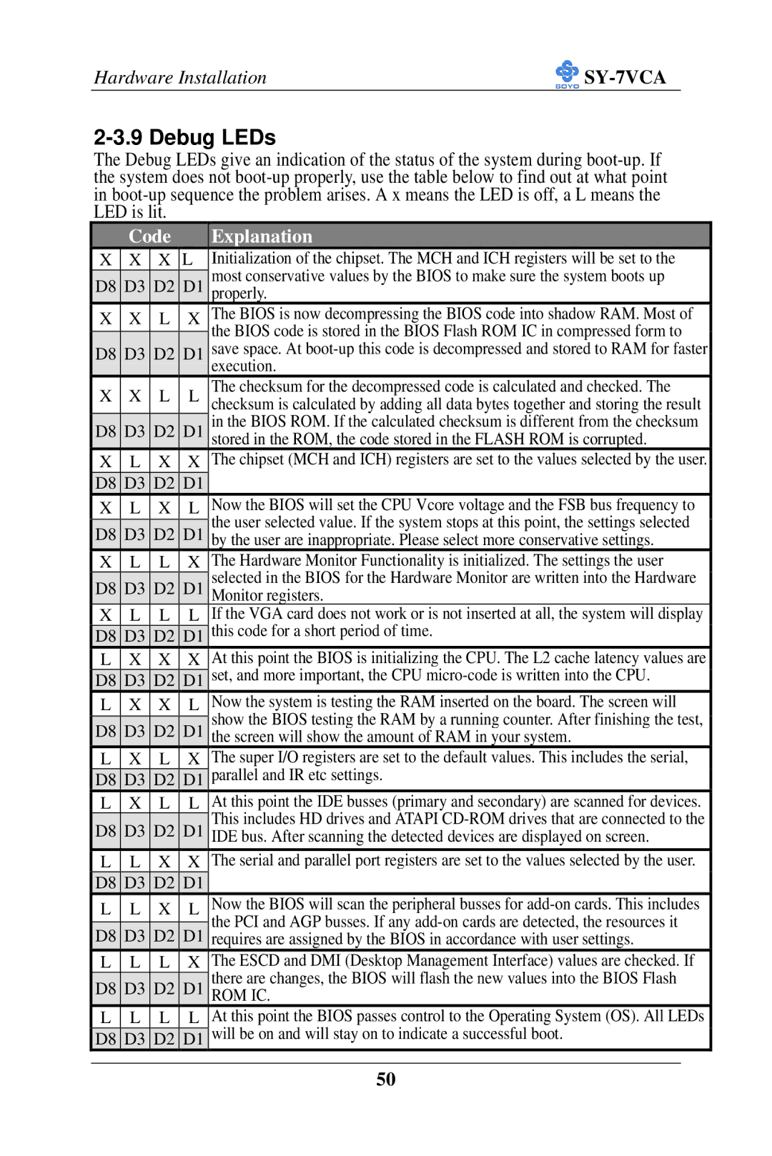
2-3.9 Debug LEDs
The Debug LEDs give an indication of the status of the system during
| Code |
| Explanation | |||
X | X | X | L | Initialization of the chipset. The MCH and ICH registers will be set to the | ||
|
|
|
| most conservative values by the BIOS to make sure the system boots up | ||
D8 | D3 | D2 | D1 | |||
properly. | ||||||
X | X | L | X | The BIOS is now decompressing the BIOS code into shadow RAM. Most of | ||
|
|
|
| the BIOS code is stored in the BIOS Flash ROM IC in compressed form to | ||
D8 | D3 | D2 | D1 | save space. At | ||
|
|
|
| execution. | ||
X | X | L | L | The checksum for the decompressed code is calculated and checked. The | ||
checksum is calculated by adding all data bytes together and storing the result | ||||||
D8 | D3 | D2 | D1 | in the BIOS ROM. If the calculated checksum is different from the checksum | ||
stored in the ROM, the code stored in the FLASH ROM is corrupted. | ||||||
X | L | X | X | The chipset (MCH and ICH) registers are set to the values selected by the user. | ||
D8 | D3 | D2 | D1 |
|
| |
X | L | X | L | Now the BIOS will set the CPU Vcore voltage and the FSB bus frequency to | ||
|
|
|
| the user selected value. If the system stops at this point, the settings selected | ||
D8 | D3 | D2 | D1 | |||
by the user are inappropriate. Please select more conservative settings. | ||||||
X | L | L | X | The Hardware Monitor Functionality is initialized. The settings the user | ||
|
|
|
| selected in the BIOS for the Hardware Monitor are written into the Hardware | ||
D8 | D3 | D2 | D1 | |||
Monitor registers. | ||||||
X | L | L | L | If the VGA card does not work or is not inserted at all, the system will display | ||
|
|
| this code for a short period of time. | |||
D8 | D3 | D2 | D1 | |||
L | X | X | X | At this point the BIOS is initializing the CPU. The L2 cache latency values are | ||
|
|
|
| set, and more important, the CPU | ||
D8 | D3 | D2 | D1 | |||
L | X | X | L | Now the system is testing the RAM inserted on the board. The screen will | ||
|
|
|
| show the BIOS testing the RAM by a running counter. After finishing the test, | ||
D8 | D3 | D2 | D1 | |||
the screen will show the amount of RAM in your system. | ||||||
L | X | L | X | The super I/O registers are set to the default values. This includes the serial, | ||
|
|
|
| parallel and IR etc settings. | ||
D8 | D3 | D2 | D1 | |||
L | X | L | L | At this point the IDE busses (primary and secondary) are scanned for devices. | ||
D8 | D3 | D2 | D1 | This includes HD drives and ATAPI | ||
IDE bus. After scanning the detected devices are displayed on screen. | ||||||
L | L | X | X | The serial and parallel port registers are set to the values selected by the user. | ||
D8 | D3 | D2 | D1 |
|
| |
L | L | X | L | Now the BIOS will scan the peripheral busses for | ||
|
|
|
| the PCI and AGP busses. If any | ||
D8 | D3 | D2 | D1 | |||
requires are assigned by the BIOS in accordance with user settings. | ||||||
L | L | L | X | The ESCD and DMI (Desktop Management Interface) values are checked. If | ||
|
|
|
| there are changes, the BIOS will flash the new values into the BIOS Flash | ||
D8 | D3 | D2 | D1 | |||
ROM IC. | ||||||
L | L | L | L | At this point the BIOS passes control to the Operating System (OS). All LEDs | ||
|
|
|
| will be on and will stay on to indicate a successful boot. | ||
D8 | D3 | D2 | D1 | |||
|
|
|
|
|
| |
50