|
|
| I | X | . |
| S | e | t | - | U | p | & |
| A | d | j u | s | t | m | e | n t |
|
|
|
|
|
|
|
|
|
|
|
|
|
|
|
|
|
|
|
|
|
|
| E n g l i s h | 25 |
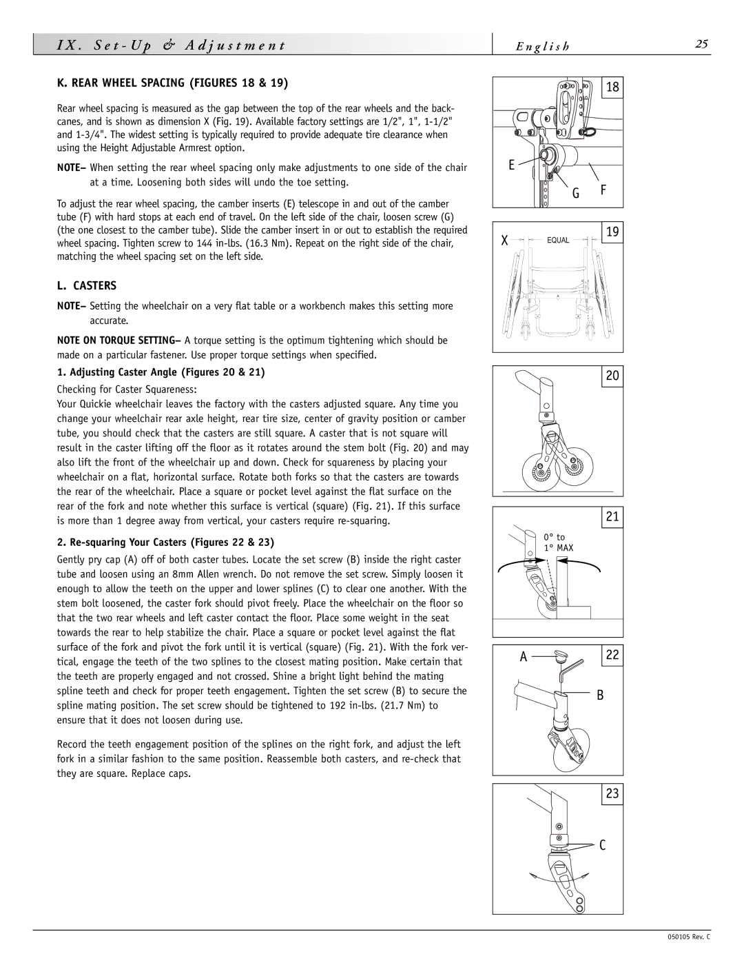
K. REAR WHEEL SPACING (FIGURES 18 & 19)
Rear wheel spacing is measured as the gap between the top of the rear wheels and the back- canes, and is shown as dimension X (Fig. 19). Available factory settings are 1/2", 1",
NOTE– When setting the rear wheel spacing only make adjustments to one side of the chair at a time. Loosening both sides will undo the toe setting.
To adjust the rear wheel spacing, the camber inserts (E) telescope in and out of the camber tube (F) with hard stops at each end of travel. On the left side of the chair, loosen screw (G) (the one closest to the camber tube). Slide the camber insert in or out to establish the required wheel spacing. Tighten screw to 144
L. CASTERS
NOTE– Setting the wheelchair on a very flat table or a workbench makes this setting more accurate.
NOTE ON TORQUE SETTING– A torque setting is the optimum tightening which should be made on a particular fastener. Use proper torque settings when specified.
1. Adjusting Caster Angle (Figures 20 & 21)
Checking for Caster Squareness:
Your Quickie wheelchair leaves the factory with the casters adjusted square. Any time you change your wheelchair rear axle height, rear tire size, center of gravity position or camber tube, you should check that the casters are still square. A caster that is not square will result in the caster lifting off the floor as it rotates around the stem bolt (Fig. 20) and may also lift the front of the wheelchair up and down. Check for squareness by placing your wheelchair on a flat, horizontal surface. Rotate both forks so that the casters are towards the rear of the wheelchair. Place a square or pocket level against the flat surface on the rear of the fork and note whether this surface is vertical (square) (Fig. 21). If this surface is more than 1 degree away from vertical, your casters require
2. Re-squaring Your Casters (Figures 22 & 23)
Gently pry cap (A) off of both caster tubes. Locate the set screw (B) inside the right caster tube and loosen using an 8mm Allen wrench. Do not remove the set screw. Simply loosen it enough to allow the teeth on the upper and lower splines (C) to clear one another. With the stem bolt loosened, the caster fork should pivot freely. Place the wheelchair on the floor so that the two rear wheels and left caster contact the floor. Place some weight in the seat towards the rear to help stabilize the chair. Place a square or pocket level against the flat surface of the fork and pivot the fork until it is vertical (square) (Fig. 21). With the fork ver- tical, engage the teeth of the two splines to the closest mating position. Make certain that the teeth are properly engaged and not crossed. Shine a bright light behind the mating spline teeth and check for proper teeth engagement. Tighten the set screw (B) to secure the spline mating position. The set screw should be tightened to 192
Record the teeth engagement position of the splines on the right fork, and adjust the left fork in a similar fashion to the same position. Reassemble both casters, and
| 18 |
E |
|
G | F |
X | 19 |
| |
| 20 |
| 21 |
| 0° to |
| 1° MAX |
A | 22 |
| B |
23
![]() C
C
050105 Rev. C