SUPERSERVER
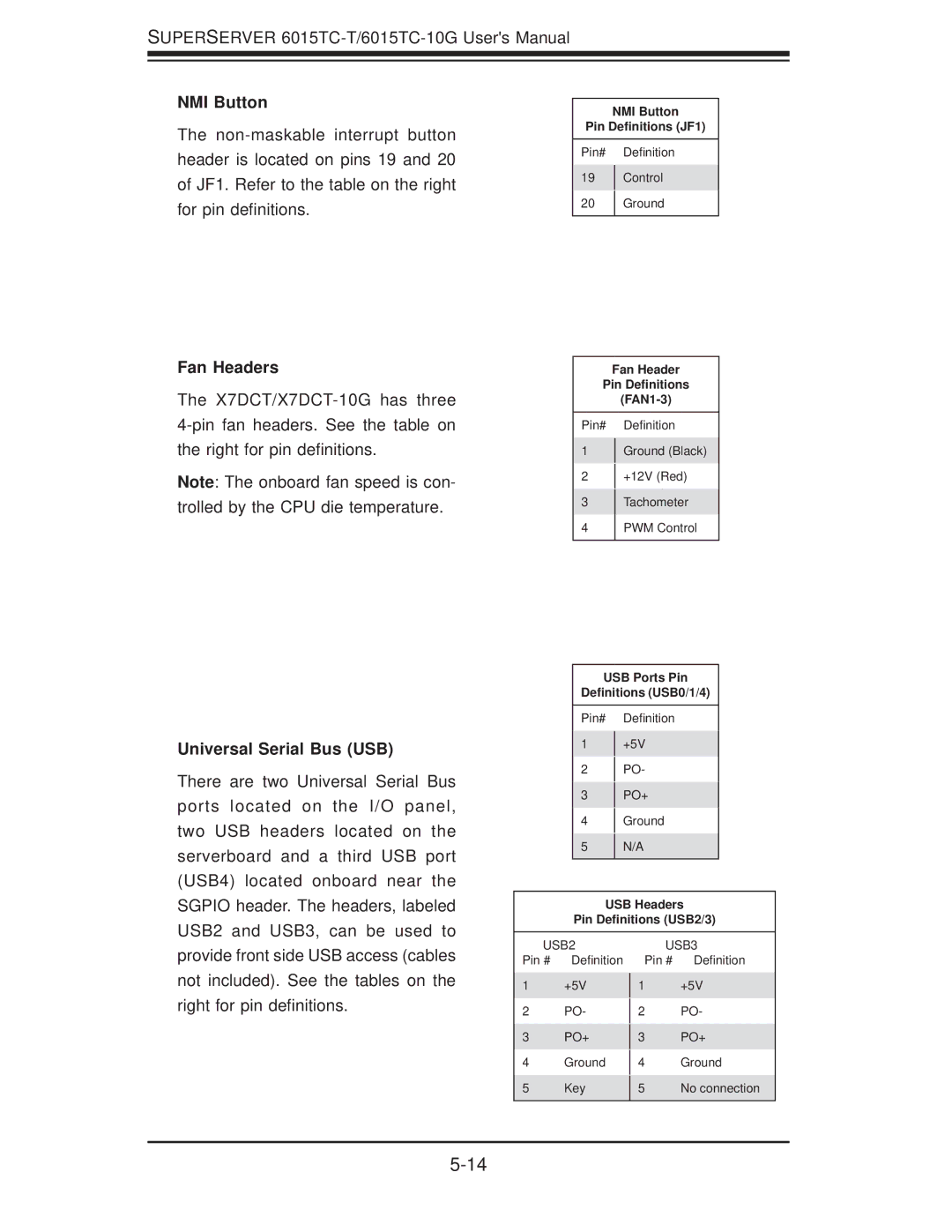
NMI Button
The
Fan Headers
The
Note: The onboard fan speed is con- trolled by the CPU die temperature.
Universal Serial Bus (USB)
There are two Universal Serial Bus ports located on the I/O panel, two USB headers located on the serverboard and a third USB port (USB4) located onboard near the SGPIO header. The headers, labeled USB2 and USB3, can be used to
NMI Button
Pin Definitions (JF1)
Pin# Definition
19Control
20Ground
Fan Header
Pin Definitions
Pin# Definition
1Ground (Black)
2+12V (Red)
3Tachometer
4PWM Control
USB Ports Pin
Definitions (USB0/1/4)
Pin# Definition
1+5V
2PO-
3PO+
4Ground
5N/A
USB Headers
Pin Definitions (USB2/3)
provide front side USB access (cables not included). See the tables on the right for pin definitions.
USB2
Pin # Definition
1+5V
2PO-
3PO+
4Ground
5Key
USB3
Pin # Definition
1+5V
2PO-
3PO+
4Ground
5No connection