Chapter 4: BIOS
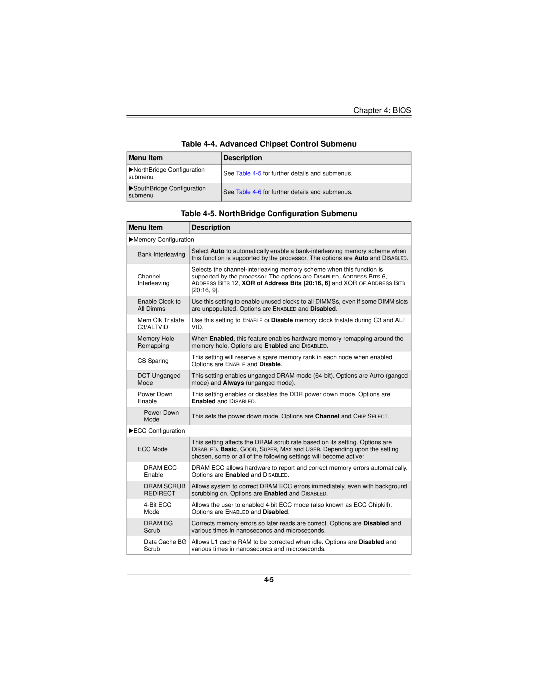
Table 4-4. Advanced Chipset Control Submenu
Menu Item | Description | |
NorthBridge Configuration | See Table | |
submenu | ||
| ||
|
| |
SouthBridge Configuration | See Table | |
submenu | ||
| ||
|
|
Table 4-5. NorthBridge Configuration Submenu
Menu Item
Description
Memory Configuration
Bank Interleaving
Channel
Interleaving
Enable Clock to All Dimms
Mem Clk Tristate C3/ALTVID
Memory Hole
Remapping
CS Sparing
DCT Unganged Mode
Power Down
Enable
Power Down
Mode
ECC Configuration
ECC Mode
DRAM ECC
Enable
DRAM SCRUB REDIRECT
Mode
DRAM BG
Scrub
Data Cache BG Scrub
Select Auto to automatically enable a
Selects the
Use this setting to enable unused clocks to all DIMMSs, even if some DIMM slots are unpopulated. Options are ENABLED and Disabled.
Use this setting to ENABLE or Disable memory clock tristate during C3 and ALT VID.
When Enabled, this feature enables hardware memory remapping around the memory hole. Options are Enabled and DISABLED.
This setting will reserve a spare memory rank in each node when enabled. Options are ENABLE and Disable.
This setting enables unganged DRAM mode
This setting enables or disables the DDR power down mode. Options are Enabled and DISABLED.
This sets the power down mode. Options are Channel and CHIP SELECT.
This setting affects the DRAM scrub rate based on its setting. Options are DISABLED, Basic, GOOD, SUPER, MAX and USER. Depending upon the setting chosen, some or all of the following settings will become active:
DRAM ECC allows hardware to report and correct memory errors automatically. Options are Enabled and DISABLED.
Allows system to correct DRAM ECC errors immediately, even with background scrubbing on. Options are Enabled and DISABLED.
Allows the user to enabled
Corrects memory errors so later reads are correct. Options are Disabled and various times in nanoseconds and microseconds.
Allows L1 cache RAM to be corrected when idle. Options are Disabled and various times in nanoseconds and microseconds.