Chapter 2: Installation
SGPIO
The
Pin# | Definition | Pin# | Definition |
1 | NC | 2 | NC |
|
|
|
|
3 | DataIn | 4 | DataOut |
5 | Load | 6 | Ground |
|
|
|
|
7 | Clock | 8 | NC1 |
1. Note: NC indicates no connection.
Power I2C
The JPI2C header is for power I2C, which may be used to monitor the status of the power supply, fan and system temperature. See the table below for pin definitions.
Pin# | Definition |
1 | Clock |
|
|
2 | Data |
3 | Power Fail |
|
|
4 | Ground |
|
|
2-7 Jumper Settings
Explanation of Jumpers
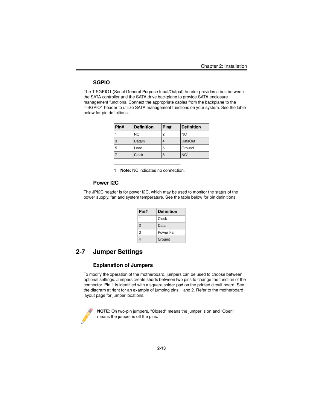
To modify the operation of the motherboard, jumpers can be used to choose between optional settings. Jumpers create shorts between two pins to change the function of the connector. Pin 1 is identified with a square solder pad on the printed circuit board. See the diagram at right for an example of jumping pins 1 and 2. Refer to the motherboard layout page for jumper locations.
NOTE: On