H8DMT/H8DMT-IBX/H8DMT-F/H8DMT-IBXF User’s Manual
NMI Button
The
Pin# | Definition |
|
|
19Control
20Ground
Universal Serial Bus Ports
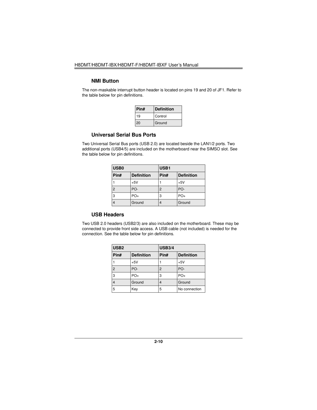
Two Universal Serial Bus ports (USB 2.0) are located beside the LAN1/2 ports. Two additional ports (USB4/5) are included on the motherboard near the SIMSO slot. See the table below for pin definitions.
USB0 |
| USB1 |
|
Pin# | Definition | Pin# | Definition |
1 | +5V | 1 | +5V |
|
|
|
|
2 | PO- | 2 | PO- |
3 | PO+ | 3 | PO+ |
|
|
|
|
4 | Ground | 4 | Ground |
|
|
|
|
USB Headers
Two USB 2.0 headers (USB2/3) are also included on the motherboard. These may be connected to provide front side access. A USB cable (not included) is needed for the connection. See the table below for pin definitions.
USB2 |
| USB3/4 |
|
Pin# | Definition | Pin# | Definition |
1 | +5V | 1 | +5V |
|
|
|
|
2 | PO- | 2 | PO- |
3 | PO+ | 3 | PO+ |
|
|
|
|
4 | Ground | 4 | Ground |
5 | Key | 5 | No connection |
|
|
|
|
