SBA-7222G-T2 Blade Module User’s Manual
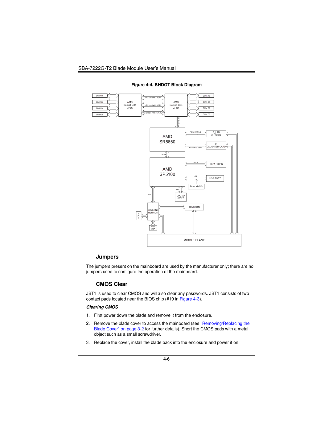
Figure 4-4. BHDGT Block Diagram
DIMM A0
DIMM B0
DIMM C0
DIMM D0
AMD
Socket G34
CPU2
HT3 Link
HT3 Link
HT3 Link
AMD
Socket G34
CPU1
DIMM A0
DIMM B0
DIMM C0
DIMM D0
DDR II
AMD
SR5650
ALink
AMD
SP5100
LPC
PCI
LPC I/O
83527
WINBOND
HERMON
Front
VGA
G_LAN |
| ||||||
|
|
|
| 2_PORTs |
| ||
|
|
|
|
|
|
| |
|
|
|
| IB | |||
DAUGHTER CARD | |||||||
SATA |
|
|
| ||||
|
|
| |||||
SATA_CONN | |||||||
|
|
|
| ||||
USB |
|
|
| ||||
|
|
| |||||
|
|
|
| USB PORT |
|
| |
|
|
|
|
|
|
| |
|
|
|
|
|
|
| |
Front KB,MS |
|
|
|
| |||
|
|
|
|
|
|
| |
|
|
|
| ||||
RTL8201N |
|
|
|
| |||
|
|
|
|
|
|
| |
MIDDLE PLANE
Jumpers
The jumpers present on the mainboard are used by the manufacturer only; there are no jumpers used to configure the operation of the mainboard.
CMOS Clear
JBT1 is used to clear CMOS and will also clear any passwords. JBT1 consists of two contact pads located near the BIOS chip (#10 in Figure
Clearing CMOS
1.First power down the blade and remove it from the enclosure.
2.Remove the blade cover to access the mainboard (see "Removing/Replacing the Blade Cover" on page
3.Replace the cover, install the blade back into the enclosure and power it on.