Chapter 5: Advanced Motherboard Setup
cables (with their locations noted) should be connected. (See the layout on page
•
•
SATA drive data cable
Control Panel cable (JF1)
Important! Make sure the the cables do not come into contact with the fans.
Connecting Power Cables
The
Connecting the Control Panel
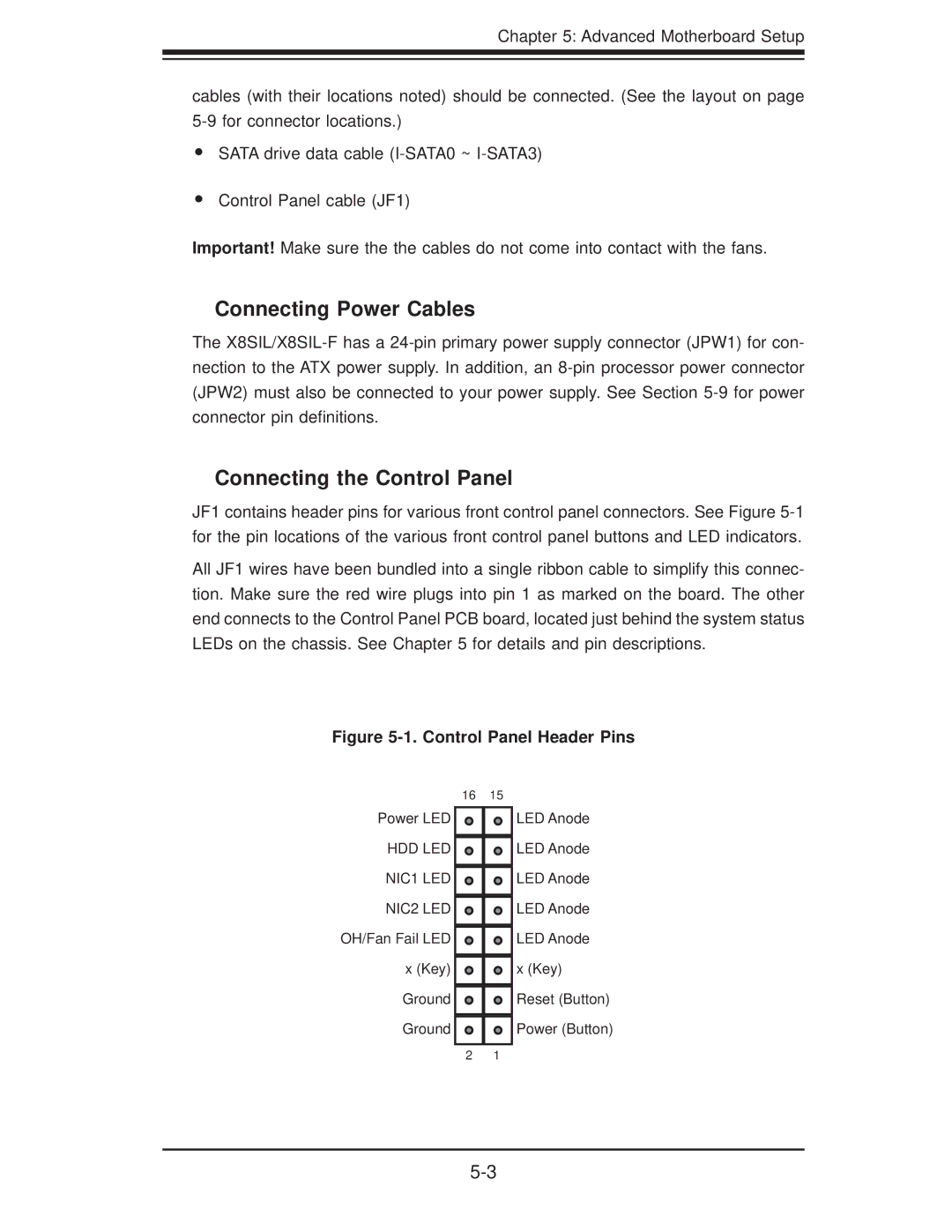
JF1 contains header pins for various front control panel connectors. See Figure
All JF1 wires have been bundled into a single ribbon cable to simplify this connec- tion. Make sure the red wire plugs into pin 1 as marked on the board. The other end connects to the Control Panel PCB board, located just behind the system status LEDs on the chassis. See Chapter 5 for details and pin descriptions.
Figure 5-1. Control Panel Header Pins
16 15
Power LED
HDD LED
NIC1 LED
NIC2 LED OH/Fan Fail LED x (Key)
Ground
Ground
2 1
LED Anode LED Anode LED Anode LED Anode LED Anode x (Key)
Reset (Button) Power (Button)