Chapter 5: Advanced Motherboard Setup
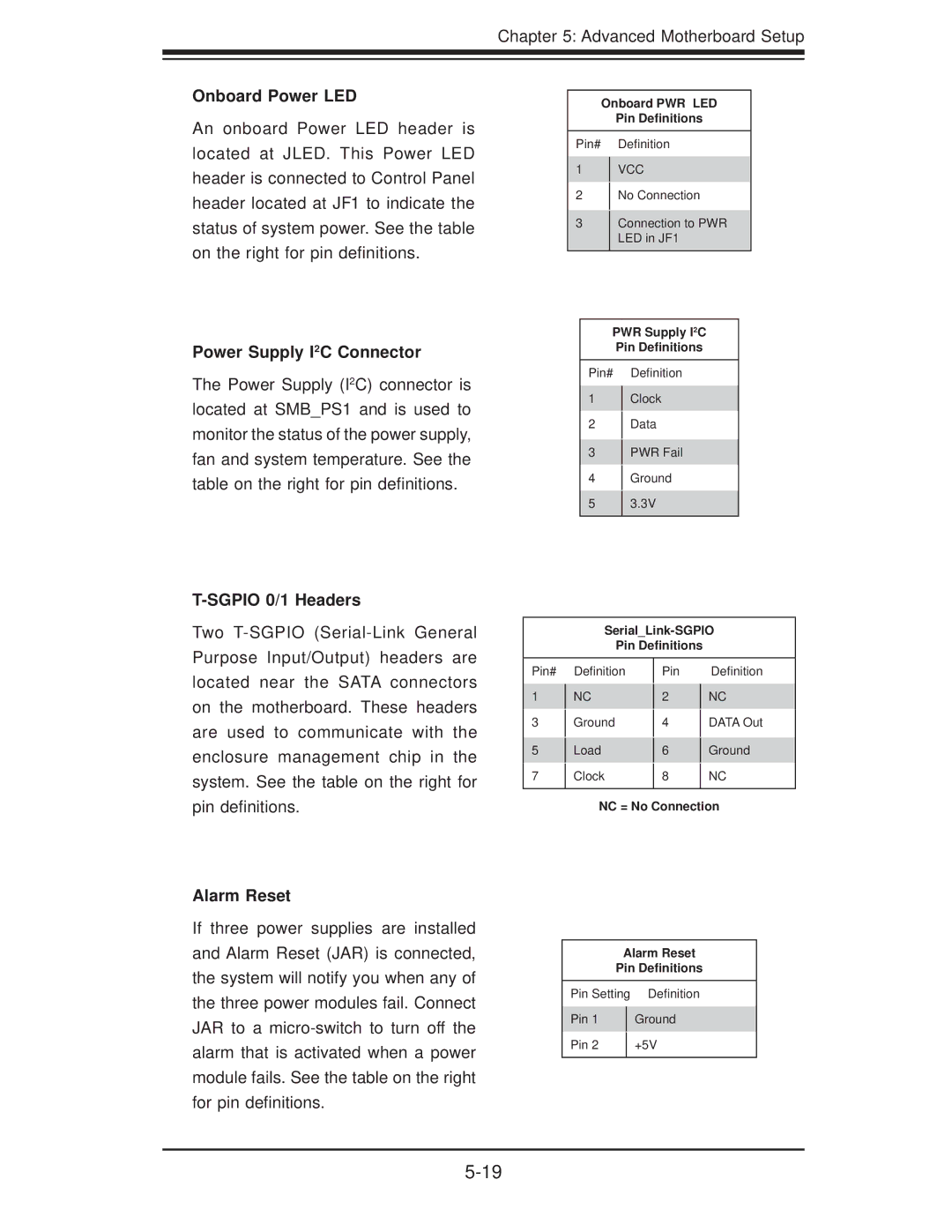
Onboard Power LED
An onboard Power LED header is located at JLED. This Power LED header is connected to Control Panel header located at JF1 to indicate the status of system power. See the table on the right for pin definitions.
Power Supply I2C Connector
The Power Supply (I2C) connector is located at SMB_PS1 and is used to monitor the status of the power supply, fan and system temperature. See the table on the right for pin definitions.
T-SGPIO 0/1 Headers
Two
Onboard PWR LED
Pin Definitions
Pin# Definition
1VCC
2No Connection
3Connection to PWR LED in JF1
PWR Supply I2C
Pin Definitions
Pin# Definition
1Clock
2Data
3PWR Fail
4Ground
53.3V
Pin Definitions
located near the SATA connectors on the motherboard. These headers are used to communicate with the enclosure management chip in the system. See the table on the right for
Pin#
1
3
5
7
Definition
NC
Ground
Load
Clock
Pin 2 4 6 8
Definition
NC
DATA Out
Ground
NC
pin definitions.
Alarm Reset
If three power supplies are installed and Alarm Reset (JAR) is connected, the system will notify you when any of the three power modules fail. Connect JAR to a
NC = No Connection
Alarm Reset | ||
Pin Definitions | ||
|
| |
Pin Setting | Definition | |
|
| |
Pin 1 |
| Ground |
|
|
|
Pin 2 |
| +5V |
|
|
|