Chapter 5: Advanced Motherboard Setup
5-9 Connector Definitions
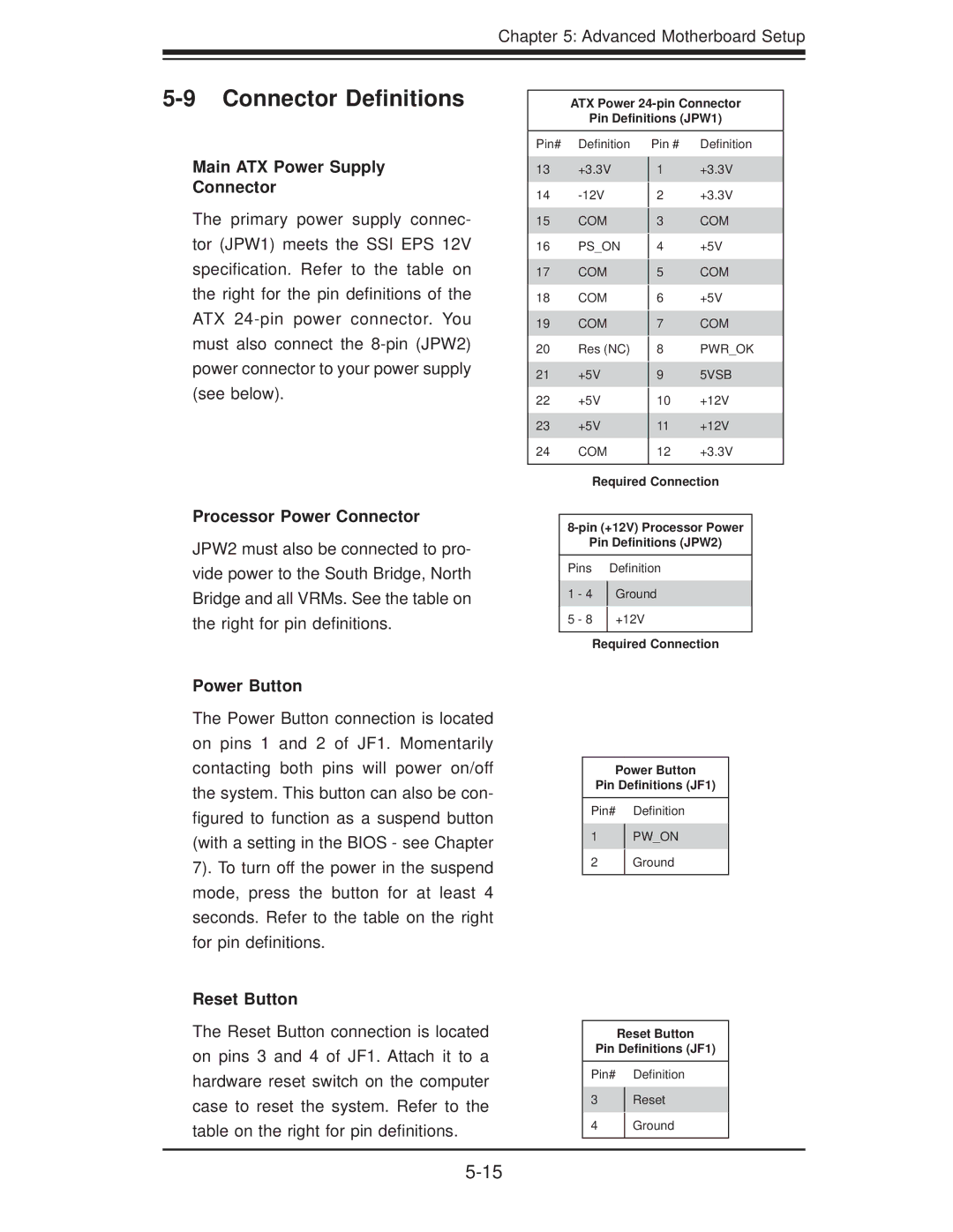
ATX Power
Pin Definitions (JPW1)
Main ATX Power Supply
Connector
The primary power supply connec- tor (JPW1) meets the SSI EPS 12V specification. Refer to the table on the right for the pin definitions of the ATX
Pin# Definition
13+3.3V
14
15COM
16PS_ON
17COM
18COM
19COM
20Res (NC)
21+5V
22+5V
23+5V
24COM
Pin # Definition
1+3.3V
2+3.3V
3COM
4+5V
5COM
6+5V
7COM
8PWR_OK
95VSB
10+12V
11+12V
12+3.3V
Processor Power Connector
JPW2 must also be connected to pro- vide power to the South Bridge, North Bridge and all VRMs. See the table on the right for pin definitions.
Power Button
The Power Button connection is located on pins 1 and 2 of JF1. Momentarily contacting both pins will power on/off the system. This button can also be con- figured to function as a suspend button (with a setting in the BIOS - see Chapter 7). To turn off the power in the suspend mode, press the button for at least 4 seconds. Refer to the table on the right for pin definitions.
Reset Button
The Reset Button connection is located on pins 3 and 4 of JF1. Attach it to a hardware reset switch on the computer case to reset the system. Refer to the table on the right for pin definitions.
Required Connection
Pin Definitions (JPW2)
Pins Definition
1 - 4 Ground
5 - 8 +12V
Required Connection
Power Button
Pin Definitions (JF1)
Pin# Definition
1PW_ON
2Ground
Reset Button
Pin Definitions (JF1)
Pin# Definition
3Reset
4Ground