Chapter 5: Advanced Motherboard Setup
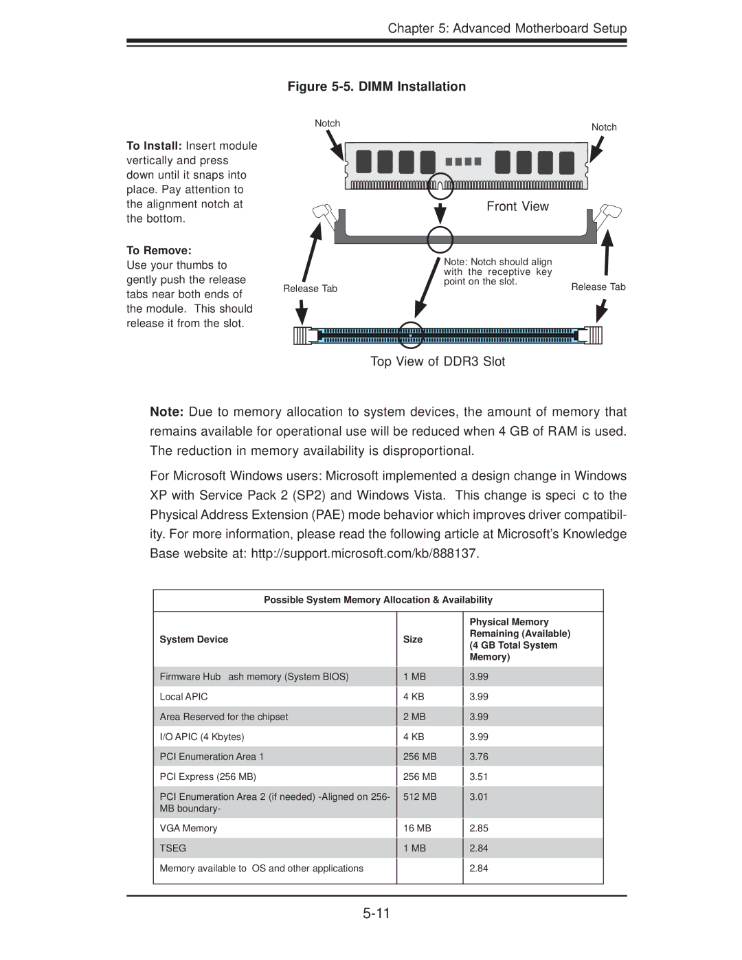
To Install: Insert module vertically and press down until it snaps into place. Pay attention to the alignment notch at the bottom.
To Remove:
Use your thumbs to gently push the release tabs near both ends of the module. This should release it from the slot.
Figure 5-5. DIMM Installation
Notch | Notch |
|
|
| Front View |
|
| Note: Notch should align |
| |
| with | the receptive key |
|
Release Tab | point on the slot. | Release Tab | |
|
| ||
Top View of DDR3 Slot
Note: Due to memory allocation to system devices, the amount of memory that remains available for operational use will be reduced when 4 GB of RAM is used. The reduction in memory availability is disproportional.
For Microsoft Windows users: Microsoft implemented a design change in Windows XP with Service Pack 2 (SP2) and Windows Vista. This change is specific to the Physical Address Extension (PAE) mode behavior which improves driver compatibil- ity. For more information, please read the following article at Microsoft’s Knowledge Base website at: http://support.microsoft.com/kb/888137.
Possible System Memory Allocation & Availability
System Device
Size
Physical Memory
Remaining (Available)
(4 GB Total System
Memory)
Firmware Hub flash memory (System BIOS) Local APIC
Area Reserved for the chipset
I/O APIC (4 Kbytes)
PCI Enumeration Area 1
PCI Express (256 MB)
PCI Enumeration Area 2 (if needed)
VGA Memory
TSEG
Memory available to OS and other applications
1MB
4KB
2MB
4KB
256 MB
256MB
512MB
16MB
1MB
3.99
3.99
3.99
3.99
3.76
3.51
3.01
2.85
2.84
2.84