Manuals
/
TC electronic SDN BHD
/
Home Audio
/
Stereo Amplifier
TC electronic SDN BHD
P2
manual
Signal Flow
Models:
P2
1
11
41
41
Download
41 pages
50.88 Kb
8
9
10
11
12
13
14
15
Troubleshooting
Specifications
Install
Signal Flow
ADMINISTRATOR’S Manual
Front Panel Configuration
Preset keys
Typical Setups
Safety
Features
Page 11
Image 11
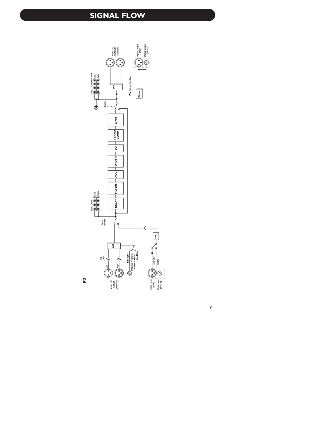
SIGNAL FLOW
9
Page 10
Page 12
Page 11
Image 11
Page 10
Page 12
Contents
ADMINISTRATOR’S Manual
Page
Voltage
Important Safety Instructions
P2 Level Pilot
For the customers in Canada
Certificate Of Conformity
Table of Contents
Concept
Features
Introduction
Daily User
Quick Start
Front Panel Overview
Bypass key
Preset keys
Wizard key
Lock key
XLR to XLR XLR to Jack Stereo
Rear Panel
Signal Flow
Connecting and Setting up the P2
Typical Setups
Wizard
Basics Front Panel
Lock Recall
Four Bypass modes are available
Front Panel Operation
Bypass
CD-ROM
Installing
Problems?
Requirements for running the TC Icon Software Editor
Generally
TC Icon Editor
Introduction
Unpacked and ready
Link
Renaming presets
Basic Operation
Library Pages
Preset Structure RECALL/STORE/DELETE
System Presets
Engine Presets
Bank Handling
Basics Preset Handling
Press the Create Clone Card key on the System/Card
Cloning P2’S
Cloning P2’s
Creating the Clone Card
System I/O
Mode
GPI Technical specifications
GPI Current voltage
Front Panel Configuration
System Front
Calibrate
Network identification
System NET page & Icon Views
UI Icon Views
Analog In, Analog Out & Out Threshold Range 0 to 20dB
Color
Main
Analog vs. Digital level
Configuration
Reference Level
Processing Modes
Loudness
Slow Window Range 0 to 20 dB
Level Trim
Ratio
Average Rate Avg Rate
Parametric Filter Broad type
Introduction
Type Selector
Gain
Type
Band
Band Limiter
Limiterappendix
Reset menu Software load
Port Conflict
Appendix Troubleshooting
Loading Preset Banks
Appendix Technical Specifications
Self Test
Name Screen Notes Input Max Scale Design Notes Default
Preset List SW
Mastering
Name Screen Notes Input Max Scale Design Notes Reserved
Live Mix
Preset List SW
Top
Page
Image
Contents