SYSTEM - I/O PAGE
Parameters on the System page can be stored and recalled via System presets and are unaffected by normal Recall operations.
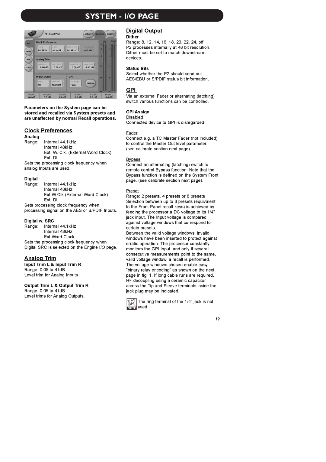
Clock Preferences
Analog
Range: Internal 44.1kHz
Internal 48kHz
Ext. W. Clk. (External Word Clock)
Ext. DI
Sets the processing clock frequency when analog Inputs are used.
Digital
Range: Internal 44.1kHz
Internal 48kHz
Ext W Clk (External Word Clock)
Ext. DI
Sets processing clock frequency when processing signal on the AES or S/PDIF Inputs.
Digital w. SRC
Range: Internal 44.1kHz
Internal 48kHz
Ext Word Clock
Sets the processing clock frequency when Digital SRC is selected on the Engine I/O page.
Analog Trim
Input Trim L & Input Trim R
Range: 0.05 to 41dB
Level trim for Analog Inputs
Output Trim L & Output Trim R
Range: 0.05 to 41dB
Level trims for Analog Outputs.
Digital Output
Dither
Range: 8, 12, 14, 16, 18, 20, 22, 24, off
P2 processes internally at 48 bit resolution. Dither must be set to match downstream devices.
Status Bits
Select whether the P2 should send out AES/EBU or S/PDIF status bit information.
GPI
Via an external Fader or alternating (latching) switch various functions can be controlled.
GPI Assign
Disabled
Connected device to GPI is disregarded.
Fader
Connect e.g. a TC Master Fader (not included) to control the Master Out level parameter. (see calibrate section next page).
Bypass
Connect an alternating (latching) switch to remote control Bypass function. Note that the Bypass function is defined on the System Front page. (see calibrate section next page).
Preset
Range: 2 presets, 4 presets or 8 presets Selection between up to 8 presets (equivalent to the Front Panel recall keys) is achieved by feeding the processor a DC voltage to its 1/4" jack input. The Input voltage is compared against voltage windows that correspond to certain presets.
Between the valid voltage windows, invalid windows have been inserted to protect against erratic operation. The processor constantly monitors the GPI Input, and only if several consecutive measurements point to the same, valid voltage window, a recall is performed. The voltage windows chosen enable easy "binary relay encoding" as shown on the next page in fig. 1. If long cable runs are required, HF decoupling using a ceramic capacitor across the Tip and Sleeve terminals inside the jack plug may be indicated.
The ring terminal of the 1/4" jack is not ![]() used.
used.
19