SLEU063
2.5VBI Decoder Interface
This interface provides a method of connecting an external VBI decoder module to the TVP5160EVM via the H3 and H4 headers. The VBI decoder may be a
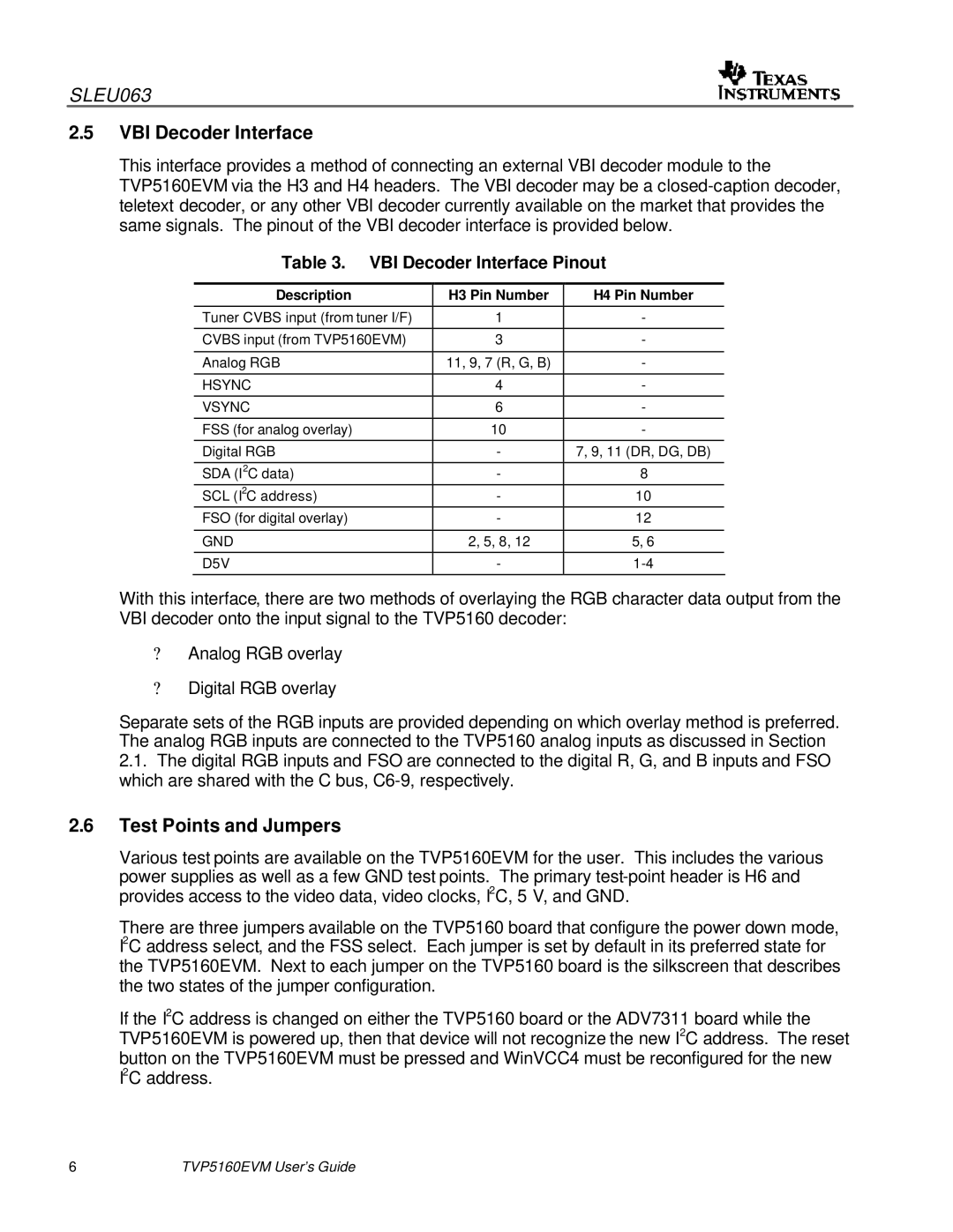
Table 3. VBI Decoder Interface Pinout
Description | H3 Pin Number | H4 Pin Number |
|
|
|
Tuner CVBS input (from tuner I/F) | 1 | - |
|
|
|
CVBS input (from TVP5160EVM) | 3 | - |
|
|
|
Analog RGB | 11, 9, 7 (R, G, B) | - |
|
|
|
HSYNC | 4 | - |
|
|
|
VSYNC | 6 | - |
|
|
|
FSS (for analog overlay) | 10 | - |
|
|
|
Digital RGB | - | 7, 9, 11 (DR, DG, DB) |
|
|
|
SDA (I2C data) | - | 8 |
SCL (I2C address) | - | 10 |
FSO (for digital overlay) | - | 12 |
|
|
|
GND | 2, 5, 8, 12 | 5, 6 |
|
|
|
D5V | - | |
|
|
|
With this interface, there are two methods of overlaying the RGB character data output from the VBI decoder onto the input signal to the TVP5160 decoder:
?Analog RGB overlay
?Digital RGB overlay
Separate sets of the RGB inputs are provided depending on which overlay method is preferred. The analog RGB inputs are connected to the TVP5160 analog inputs as discussed in Section
2.1. The digital RGB inputs and FSO are connected to the digital R, G, and B inputs and FSO which are shared with the C bus,
2.6Test Points and Jumpers
Various test points are available on the TVP5160EVM for the user. This includes the various power supplies as well as a few GND test points. The primary
There are three jumpers available on the TVP5160 board that configure the power down mode, I2C address select, and the FSS select. Each jumper is set by default in its preferred state for the TVP5160EVM. Next to each jumper on the TVP5160 board is the silkscreen that describes the two states of the jumper configuration.
If the I2C address is changed on either the TVP5160 board or the ADV7311 board while the TVP5160EVM is powered up, then that device will not recognize the new I2C address. The reset
button on the TVP5160EVM must be pressed and WinVCC4 must be reconfigured for the new I2C address.
6 | TVP5160EVM User’s Guide |