Error! Style not defined. Error! Style not defined. | 4 Replacement Procedures |
4.1General
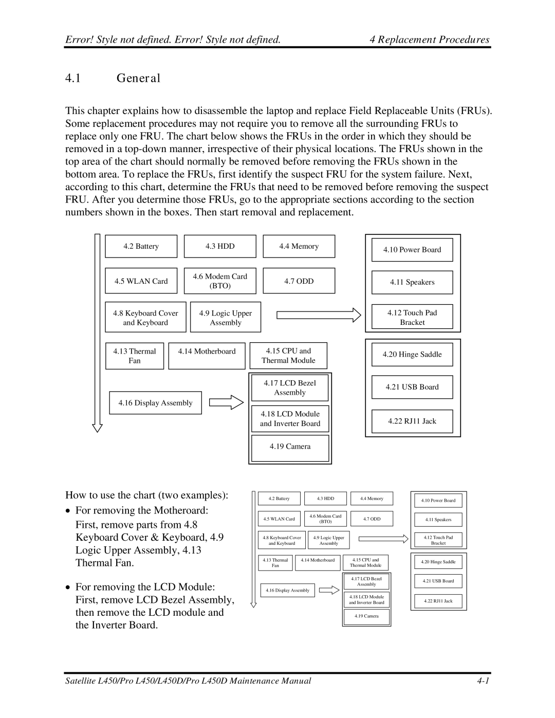
This chapter explains how to disassemble the laptop and replace Field Replaceable Units (FRUs). Some replacement procedures may not require you to remove all the surrounding FRUs to replace only one FRU. The chart below shows the FRUs in the order in which they should be removed in a
4.2 Battery
4.5WLAN Card
4.8Keyboard Cover and Keyboard
4.3HDD
4.6Modem Card (BTO)
4.9Logic Upper Assembly
4.4Memory
4.7ODD
4.10 Power Board |
4.11 Speakers |
4.12 Touch Pad |
Bracket |
4.13 Thermal | 4.14 Motherboard |
Fan
4.16 Display Assembly
4.15CPU and
Thermal Module
4.17LCD Bezel Assembly
4.18LCD Module and Inverter Board
4.19Camera
4.20 Hinge Saddle |
4.21 USB Board |
4.22 RJ11 Jack |
How to use the chart (two examples):
∙ For removing the Motheroard: |
First, remove parts from 4.8 |
4.2 Battery |
| 4.3 HDD |
| 4.4 Memory |
|
|
|
|
|
|
|
|
|
|
4.5 WLAN Card |
| 4.6 Modem Card |
| 4.7 ODD |
| (BTO) |
| ||
|
|
|
| |
|
|
|
|
|
4.10 Power Board |
4.11 Speakers |
Keyboard Cover & Keyboard, 4.9 |
Logic Upper Assembly, 4.13 |
Thermal Fan. |
∙ For removing the LCD Module: |
First, remove LCD Bezel Assembly, |
then remove the LCD module and |
the Inverter Board. |
| 4.8 Keyboard Cover |
|
| 4.9 Logic Upper | ||||
| and Keyboard |
|
|
| Assembly | |||
|
|
|
|
|
|
|
|
|
|
|
|
|
|
|
|
| |
| 4.13 Thermal |
|
| 4.14 Motherboard |
| |||
| Fan |
|
|
|
|
|
|
|
|
|
|
|
|
|
| ||
|
|
| ||||||
|
|
|
|
|
|
|
|
|
| 4.16 Display Assembly |
| ||||||
|
|
| ||||||
|
|
|
|
|
|
|
|
|
|
|
|
|
|
|
|
|
|
4.15CPU and
Thermal Module
4.17LCD Bezel Assembly
4.18LCD Module and Inverter Board
4.19Camera
4.12 Touch Pad |
Bracket |
4.20 Hinge Saddle |
4.21 USB Board |
4.22 RJ11 Jack |
Satellite L450/Pro L450/L450D/Pro L450D Maintenance Manual |