4 Replacement Procedures | Error! Style not defined. Error! Style not defined. |
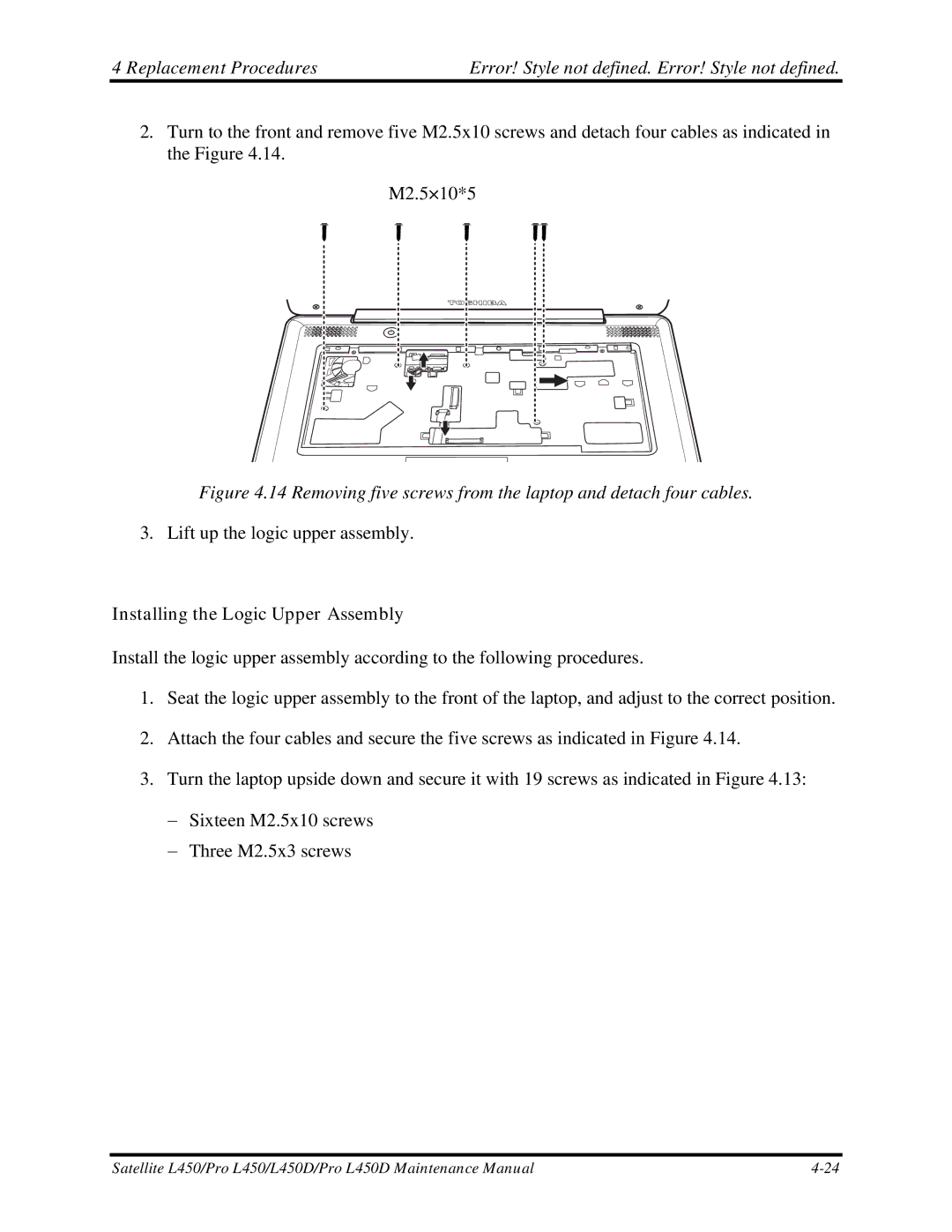
2.Turn to the front and remove five M2.5x10 screws and detach four cables as indicated in the Figure 4.14.
M2.5×10*5
Figure 4.14 Removing five screws from the laptop and detach four cables. 3. Lift up the logic upper assembly.
Installing the Logic Upper Assembly
Install the logic upper assembly according to the following procedures.
1.Seat the logic upper assembly to the front of the laptop, and adjust to the correct position.
2.Attach the four cables and secure the five screws as indicated in Figure 4.14.
3.Turn the laptop upside down and secure it with 19 screws as indicated in Figure 4.13:
−Sixteen M2.5x10 screws
−Three M2.5x3 screws
Satellite L450/Pro L450/L450D/Pro L450D Maintenance Manual |