Connection
Before connection
•Read the owner’s manual of the device to be connected to the projector.
•Some types of computer cannot be used connected to this projector. Check for an RGB output terminal, supported signal p.69 , etc.
•Turn off the power of both devices before connection.
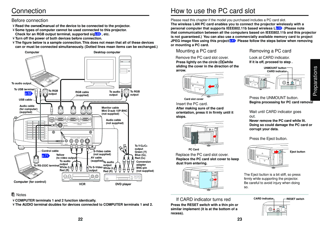
•The figure below is a sample connection. This does not mean that all of these devices can or must be connected simultaneously. (Dotted lines mean items can be exchanged.)
How to use the PC card slot
Please read this chapter if the model you purchased includes a PC card slot.
The wireless LAN PC card enables you to connect the projector wirelessly with a personal computer that supports IEEE802.11b based wireless LAN. p.33 (Please note that communication between all the computers based on IEEE802.11b and this projector is not guaranteed.) You can also use a commercially available memory card to project JPEG image files using this projector. p.41 Please follow the steps below when removing or mounting a PC card.
Computer | Desktop computer |
■Mounting a PC card
qRemove the PC card slot cover.
Press lightly on the circle (“O”) while sliding the cover in the direction of the arrow.
■Removing a PC card
qLook at CARD indicator.
If it is off, proceed to step r.
UNMOUNT button
CARD indicator
To audio output
To USB terminal
p.52
USB cable
Audio cable (for computer) (supplied)
To RGB | RGB cable | |
output | ||
(supplied) | ||
|
USB
MONITOR1 COMPUTER 2
( Y/PB/PR )
CONTROL
VIDEO
To audio | To RGB |
output | output |
Monitor cable
Mini
Audio cable (not supplied)
Card slot cover
wInsert the PC card.
After making sure of the card orientation, press it in firmly until it stops.
wPress the UNMOUNT button.
Begins processing for PC card removal
eWait until CARD indicator goes out.
Never remove the PC card while lit. Doing so could damage the PC card or corrupt your data.
rPress the Eject button.
Preparations
AUDIO R - AUDIO - L VIDEO
![]() Control cable
Control cable
p.71 | Yellow |
| (to video output) |
To audio output ![]() White (L) Red (R)
White (L) Red (R)
AV cable (supplied) To audio
| output |
To | |
output | Red (R) |
| |
To Y/CB/CR output Green (Y) Blue (CB), Red (CR)
Conversion adapter
PC Card
eReplace the PC card slot cover.
Replace the PC card slot cover to keep dust from entering.
Eject button
The Eject button is a bit stiff, so press firmly while supporting the projector.
Computer (for control)
VCR | DVD player |
![]() Notes
Notes
•COMPUTER terminals 1 and 2 function identically.
•The AUDIO terminal doubles for devices connected to COMPUTER terminals 1 and 2.
Be careful to avoid injury when doing so.
■ If CARD indicator turns red | CARD indicator |
|
|
| RESET switch |
|
|
| |||
|
|
|
|
Press the RESET switch with a thin pin or similar implement (it is at the bottom of a recess).
22 | 23 |