TLP-MT7E
Safety Precautions
Save Original Packing Materials
Avoid Volatile Liquid
Moisture Condensation
Power Sources
Source of Light
Ventilation
Important Safety Instructions
Heat Cleaning Overloading
Power-Cord Protection
Water and Moisture
Accessories
Object and Liquid Entry
Do not place the product vertically
Stack Inhibited
Damage Requiring Service
Replacement Parts
Safety Check
Servicing
Power supply cord selection
Plug Configuration Plug type Line voltage
220
Contents
Names of each part on the main unit
Lamp indicator 25 28 Temp indicator 64 Busy indicator
Selection button
Exit button
Menu button
Control connector 24 RS-232C connector
Component in connector 21
Video connector
Audio in jack Audio input 21 23 ø 3.5mm stereo mini-jack
Names of each part on the remote control
Install the batteries
Loading batteries
Open the cover
Attach the cover
Remote control operation
Floor-mounted projector placement
Viewer
Floor-mounted projector placement Contents
Connect the power cord
Power cord Supplied
Take off the lens cover
Obtained and hold down the foot adjuster release button
Turn clockwise to lift up Turn counterclockwise to lower
Ceiling-mounted projector placement
Ceiling-mounted rear projection
Connecting video equipment
Video equipment DVD player, etc
Connecting video equipment
Connecting a computer
Connection Installationand
Projector operation control by a computer
Playback mode
Projection on the screen
Press ON/STANDBY
Turn on the connected equipment and put it
Signal sent from the computer
Select the input source
Press the Input button repeatedly to select it
Icon of the input source selected appears
Adjust the picture size by turning
Focusing ring
Press VOL/ADJ +/ to adjust volume
Zooming lever
Turning the power off
Press ON/STANDBY after using the projector
Press ON/STANDBY again
Remote control Control panel
Correcting the keystone distortion
Press Auto Keystone
Main unit side
Remote control
Icon appears in the resize mode
Enlarging the picture size
Press Resize
Icon Appears in the mute mode
Cutting off the picture and sound temporarily
Press Mute
Sound and picture are cut off temporarily
Appears in the freeze mode
Freezing the picture
Press Freeze
Picture freezes
Adjusting the picture automatically Computer input
Input full screen video signals from the input
Source computer and project the image
Press Auto SET
Displaying PIP Sub-pictures
Press PIP
Sub-picture is displayed
Press the PIP button again to turn off the sub-picture
Displaying Information
Press Call
Input
Lamp time
Adjustments and settings on the menu screen
Quick Menu
Operating the menu screen
Quick Menu adjustments and settings
You can set the basic setting used frequently
Press Menu
Quick Menu appears
Settings
Press VOL/ADJ +/ to adjust and set
Remote control Main unit side
Sub-menu screen of input source setting appears
Press Enter
Press VOL/ADJ +/- to select the type of input source
Press Exit to return to the Quick Menu
Use the selection buttons / to select a language
After the adjustments and settings are
Finished, press Exit
Menu screen disappears
Full Menu adjustments and settings Picture
Press Menu twice
Use the selection buttons / to select
Signal format
Video mode Yes
Frequency Adjust vertical stripes Adjust vertical stripes
Yes Settable No Not displayed
Screen size Computer input
Screen size Video input, S-Video input, Y/PB/PR input
Press Exit to return to the Full Menu
Sub-menu of selected items appears PositionLevel
Use the selection buttons / to select setting items
Signal format Y/PB/PR input
Video mode Video input, S-Video input
Sub-menu of selected items appears
Enter
Full Menu settings Audio
Use the selection buttons To select Setting items
Use the selection button To display Audio menu
To move back to it
After the settings are finished, press Exit
When set to Off, no sound is produced from the speakers
Speaker output
Channel select
Full Menu settings Keystone
Use the selection buttons To display Keystone menu
Sub-menu of Horizontal reference value reset appears
Horizontal reference value is reseted
Yes and press Enter
Keystone
Full Menu settings Display
When pressed once, the Quick Menu screen appears. When
Use the selection buttons To display Display menu
Sub-menu of Language appears
Portuguê s Portuguese
No signal background Setting of screen of no signal input
Menu position
Start-up screen
Full Menu settings Default setting
Use the selection buttons To display Default setting menu
When pressed once, the Quick Menu screen appears. When
Pressed twice, the Picture screen of the Full Menu appears
Sub-menu of Input source setting appears
Video
Use the selection buttons / to select the projection mode
Sub-menu of Projection mode appears
Rear ceiling
Ceiling-mounted front projection
No signal power off
Power on
Press VOL/ADJ +/ to set
Full Menu settings Factory reset mode
Factory default setting
Picture menus for the each input to
Menu screen disappears
PIP menu setting
Setting items, then press VOL/ADJ +/ to set
Menu screen disappears
Indicator
Trouble indications
Air filter cleaning
Unplug the power cord
Clean the air filter
Take off the air filter cover
Assemble the air filter
Mount the air filter cover
Air filter Filter frame Air filter cover
Lens and main unit cleaning
Cleaning the lens
Cleaning the main unit
Replacing the intake, exhaust fans and air filter
Lamp replacement
Wait until the lamp gets cold enough
Take off the lamp cover on
Bottom panel
Reset the lamp timer
Load a new lamp
Attach the lamp cover
Slide the cover in place and tighten two screws
Before calling service personal
Before calling service personal
Mini D-sub 15pin connector
Do not connect anything
Timing chart
Mode Resolution Clock Pixels KHz MHz Lines
Mode Fh kHz Fv Hz Fsc MHz
15.73 480i 59.94
15.63 480p 31.47 59.94
15.63 25 or 720p 45.00 60.00
Pin No Signal Description Method
Signal ground
Items/Status Selection Adjustment
Computer Video/S-Video Command Power
Computer Video/S-Video Command Picture Position
Picture mode Bright
Picture mode Standard
Video mode Auto
Computer Video/S-Video Command Audio Speaker output
Horizontal reference value reset
No signal background Logo
Off
Computer Video/S-Video Command Display
Default Input source setting Setting
Projection mode Standard
No signal power off Off
Computer Video/S-Video Command Volume Increase
Enlargement reset
Decrease
Input select Toggle
Specifications
Replacement lamp


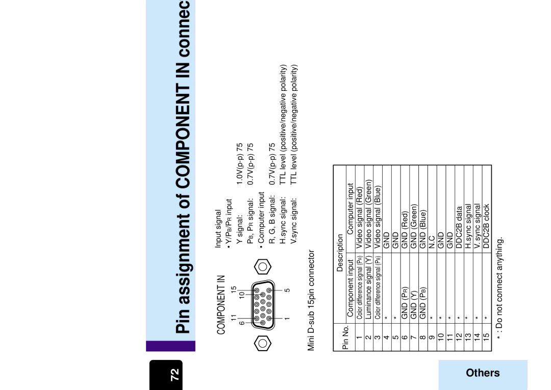
 Pin assignment of COMPONENT IN connector