Packaged Heat Pumps
Introduction
American Standard Inc. All rights reserved
Contents
Features and Benefits
Flexible Applications
Easy Access Low Voltage Terminal Board
Standardized Components
Micro Controls
ReliaTel Micro
Economizer
Hinged Access Doors
Phase Monitor
Comm-3/4Trane Communication Interface
VariTrac
Quality And Reliability Testing
We test designs at our factory not on our customers
Clearance Requirements
Barometric Relief
Condensate Trap
Unit Pitch
Heating Capacity Step
Accessory Selection
Cooling Capacity Step
Air Delivery Selection
Selection Procedure IP Units
Model Number Description
060 11 12,13
General Data
Table GD-1 General Data
Table PD-1a Gross Cooling Capacities MBH WSC060AD,T IP
Performance Data
Table PD-1 Gross Cooling Capacities kW WSC060AD,T SI
Table PD-2 Gross Cooling Capacities kW WSC072AD,T SI
Table PD-2a Gross Cooling Capacities MBH WSC072AD,T IP
Table PD-3 Gross Cooling Capacities kW WSC090AD,T SI
Table PD-3a Gross Cooling Capacities MBH WSC090AD,T IP
Table PD-4 Gross Cooling Capacities kW WSC120AD,T SI
Table PD-4a Gross Cooling Capacities MBH WSC120AD,T IP
Performance Data
At Indicated Indoor Dry Bulb Temp C
Performance Data
10.4 10.8
10.0 10.4
10.2 10.6
10.1 10.6 11.1
2 HP Standard Motor
Nom kW Standard Motor & Hi Static Drive
2 HP Standard Motor & Static Drive
Hi Static Drive
Drive
Nom kW Standard Motor Hi Static Drive
Nom kW Standard Motor
2 HP Std Motor & Drive
2 HP Std Motor 2 HP Standard Motor Hi Static Drive
Nom kW Standard Motor Drive
Nom kW Over-Sized Motor
HP Over-Sized Motor & Hi Static Drive
3260 1002
Nom kW Standard Motor & Drive Hi Static Drive
External Static Pressure Pascals 275 300 325 350 375 M3/h
1920 1002
HP Standard Motor Hi Static Drive
Nom kW Std Motor Nom kW Standard Motor
Nom kW Over-Sized Motor & Hi Static Drive
HP Standard Motor
2400 1051
Nom kW Standard Motor Nom kW OS
HP Over-Sized Motor Hi Static Drive
HP Standard Motor & Low Static Drive
Nom kW Standard Motor & Low Static Drive
Nom kW Standard Motor & High Static Drive
HP Standard Motor & High Static Drive
807 844
HP Std Motor & Drive
Table PD-20 Over-Sized Motor & Drive Sheave/Fan Speed RPM
Table PD-21 Sound Power Level dB ref -12Watts
Table PD-17 Standard Motor & Sheave/Fan Speed RPM
3400 4080 3260
Econimizer with
OA/RA Dampers2
4080 4890
Table PD-24 Auxiliary Electric Heat Capacity
Table PD-24a Auxiliary Electric Heat Capacity
3400 M 3/H 4100 M 3/H 5100 M 3/H 6800 M 3/H Stages
Variation From Nominal Airflow Temperature Rise Multiplier
Ton
10.9 11.3 12.1
Controls
Integrated Comfort System Sensors available
342-456
Table ED-1 Unit Wiring
Electrical Data
180-220
10.9 13.0
KW Rating
380 / 415 Volts
14.4 17.2
108
Volts Phase
380-415
Compressor Motor Condenser Fan Motor Unit Amps Model No
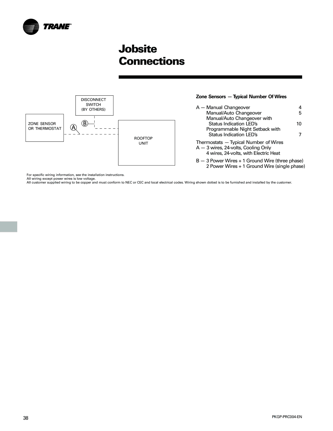
Wires, 24-volts, with Electric Heat
Jobsite Connections
Dimensional
DataWSC060
DataWSC060
DataWSC072-120
DataWSC072-120
WSC072-120 Roof Curb
Accessories
WSC060 Barometric Relief Damper
Dimensional Options
WSC072-120
Table W-2a Accessory Net Weights1, 2 lbs
Weights
Table W-2 Accessory Net Weights1, 2 kg
Mechanical Specifications
Remote Potentiometer
Electric Heaters
Roof Curb
Manual Outside Air Damper
Comm-5 LonTalk Communication Interface
Differential Pressure Switches
COMM3/4Trane Communications Interface
Zone Sensors
PKGP-PRC004-EN
PKGP-PRC004-EN
Supersedes PL-UN-000-PKGP-PRC004-EN-12-03
Literature Order Number
File Number PL-UN-000-PKGP-PRC004-EN-02-04
Stocking Location Webb/Mason 02-04 Electronic Only