Deployment & Installation | RSSI Command and Antenna Alignment |
RSSI Command and Antenna Alignment
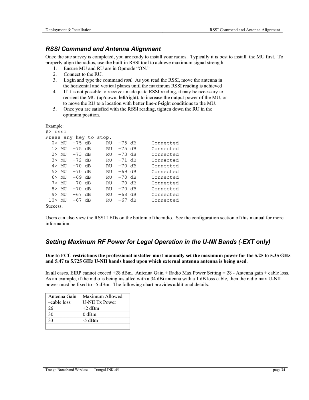
Once the site survey is completed, you are ready to install your radios. Typically it is best to install the MU first. To properly align the radios, use the
1.Ensure MU and RU are in Opmode “ON.”
2.Connect to the RU.
3.Login and type the command rssi. As you read the RSSI, move the antenna in the horizontal and vertical planes until the maximum RSSI reading is achieved
4.If it is not possible to receive an adequate RSSI reading, it may be necessary to reorient the MU (up/down, left/right), to increase the output power of the MU, or to move the RU to a location with better
5.Once you are satisfied with the RSSI reading, tighten down the RU in the optimum position.
Example: |
|
|
|
|
|
|
#> rssi |
|
|
|
|
|
|
Press any key to stop. | Connected | |||||
0> MU | RU | |||||
1> MU | RU | Connected | ||||
2> MU | RU | Connected | ||||
3> MU | dB | RU | Connected | |||
4> MU | dB | RU | Connected | |||
5> MU | dB | RU | Connected | |||
6> MU | dB | RU | Connected | |||
7> MU | dB | RU | dB | Connected | ||
8> MU | dB | RU | dB | Connected | ||
9> MU | dB | RU | dB | Connected | ||
10> MU | dB | RU | dB | Connected | ||
Success. |
|
|
|
|
|
|
Users can also view the RSSI LEDs on the bottom of the radio. See the configuration section of this manual for more information.
Setting Maximum RF Power for Legal Operation in the
Due to FCC restrictions the professional installer must manually set the maximum power for the 5.25 to 5.35 GHz and 5.47 to 5.725 GHz
In all cases, EIRP cannot exceed +28 dBm. Antenna Gain + Radio Max Power Setting = 28 - Antenna gain + cable loss. As an example, if the radio is being installed with a 34 dBi antenna with a 1 dB loss cable, then the radio max
Antenna Gain | Maximum Allowed |
26 | +2 dBm |
30 | 0 dBm |
33 | |
|
|
Trango Broadband Wireless — | page 34 |
