Test Procedures | Test Procedures |
SPEED INCLINE CALIBRATION TEST
Enter Calibration Mode by holding the Up and Down keys while inserting the safety key. The message center window displays: Calibration, Press Start
NOTE: In calibration mode, it is possible to check if the speed sensor
is reading all the front roller magnets: The Met light will light when a magnet is in front of the sensor. Move the belt slowly with your foot.
Press Start/Reset to begin calibration
Treadmill will elevate and speed up/slow down. Wait for belt to stop. Message center window will display: Successful, or indicate error area Remove and reinsert safety key. Check operation of treadmill
GROUNDED OUTLET TEST
This test is very important for optimal HRC and incline operation. Set voltmeter for Volts AC
Place 1 lead in the right side of the outlet (hot) Place l lead in the ground plug
A properly grounded outlet will read 120 VAC
AMP DRAW TEST
This test is a good indicator of the wear condition of the belt and deck, and the need for lubrication. The treadmill circuit breaker will trip at 20 amps, so
be sure the voltmeter you are using is rated for at least 20 amps when you are
AC Amp Draw Procedure
This procedure requires an AC
2.5 mph without load | 2.0 | - 2.5 AMPS AC |
with load | 2.75 - 3.75 AMPS AC | |
5.0 mph without load | 3.5- 4.0 AMPS AC | |
with load | 5.0 | - 7.0 AMPS AC |
DC Amp Draw Procedure
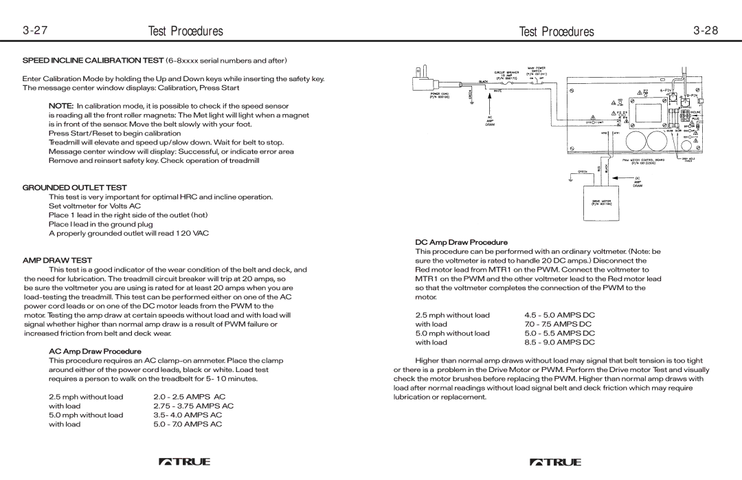
This procedure can be performed with an ordinary voltmeter. (Note: be sure the voltmeter is rated to handle 20 DC amps.) Disconnect the Red motor lead from MTR1 on the PWM. Connect the voltmeter to MTR1 on the PWM and the other voltmeter lead to the Red motor lead so that the voltmeter completes the connection of the PWM to the motor.
2.5 mph without load | 4.5 - 5.0 AMPS DC |
with load | 7.0 - 7.5 AMPS DC |
5.0 mph without load | 5.0 - 5.5 AMPS DC |
with load | 8.5 - 9.0 AMPS DC |
Higher than normal amp draws without load may signal that belt tension is too tight or there is a problem in the Drive Motor or PWM. Perform the Drive motor Test and visually check the motor brushes before replacing the PWM. Higher than normal amp draws with load after normal readings without load signal belt and deck friction which may require lubrication or replacement.