Learning The Basics | Assembly & Belt Adjustment |
THE BASICS
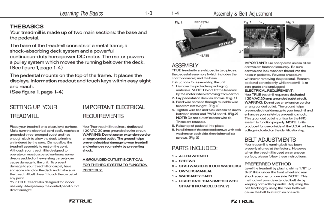
Your treadmill is made up of two main sections: the base and the pedestal.
The base of the treadmill consists of a metal frame, a
The pedestal mounts on the top of the frame. It places the displays, information readout and touch keys within easy sight and reach.
(See figure 1, page
SETTING UP YOUR | IMPORTANT ELECTRICAL |
TREADMILL | REQUIREMENTS |
Fig. 1 | PEDESTAL |
2
![]() BASE
BASE
ASSEMBLY
TRUE treadmills are shipped in two pieces: the pedestal assembly (which includes the control console) and the base.
Instructions for assembling the unit:
1. | Remove the protective packaging |
| materials. NOTE: Do not lift the treadmill |
| by the motor when removing from carton! |
2. | Lay pedestal on deck as shown. (Fig. 1) |
3. | Feed wire harness through reusable wire |
| ties from left to right. (Fig. 2) |
4. | Tighten wire ties and tuck excess tie down |
| between motor and PWM board. (Fig.2) |
| NOTE: Do not cut off excess wire tie. |
| These are reusable. |
Fig. 2 | 1 | Fig. 3 |
IMPORTANT: Do not operate unless all six screws are fastened securely. Be sure screws and lock washers thread into the holes in pedestal. Reverse procedure whenever removing the pedestal. Remove pedestal console only while treadmill is at zero grade and unplugged.
ELECTRICAL REQUIREMENT:
Your TRUE treadmill requires a dedicated
120 VAC 20 amp grounded outlet circuit. WARNING: Do not use an extension cord or an ungrounded outlet. The ground helps prevent electrical damage to your treadmill and enhances your safety by preventing shock. This grounded outlet is critical for the HRC system to function properly. NOTE: Units
Place your treadmill on a clean, level surface. Make sure the electrical cord easily reaches a grounded
Your TRUE treadmill is designed for indoor use only. Always keep the control panel out of direct sunlight.
Your True treadmill requires a dedicated
120 VAC 20 amp grounded outlet circuit. WARNING: Do not use an extension cord or an ungrounded outlet. The ground helps prevent electrical damage to your treadmill and enhances your safety by preventing shock.
A GROUNDED OUTLET IS CRITICAL
FOR THE HRC SYSTEM TO FUNCTION
PROPERLY.
5. | Raise top of pedestal into place. |
6. | Install three of the enclosed screws with lock |
| washers on each side, then tighten all six |
| screws. (Fig. 3) |
PARTS INCLUDED:
1 - ALLEN WRENCH
6 - SCREWS
6- STAR WASHERS (LOCK WASHERS)
1 - OWNERS MANUAL
1 - WARRANTY CARD
1 - HEART RATE TRANSMITTER WITH STRAP (HRC MODELS ONLY)
produced for use outside of the U.S.A. will have voltage indicated on the identification tag.
BELT ADJUSTMENTS
Your treadmillÕs running belt has been properly aligned at the factory. However, when the treadmill is used on an uneven surface, please follow these instructions:
PREFERRED METHOD
Level the treadmill by placing shims 1/8Ó to 3/8Ó thick under the front wheel and rear shock absorber on one side. NOTE: This method will provide extended belt life by keeping both rollers parallel. Adjusting the belt tracking by using the roller bolts will cause the belt to stretch on one side.