Termination Clearances
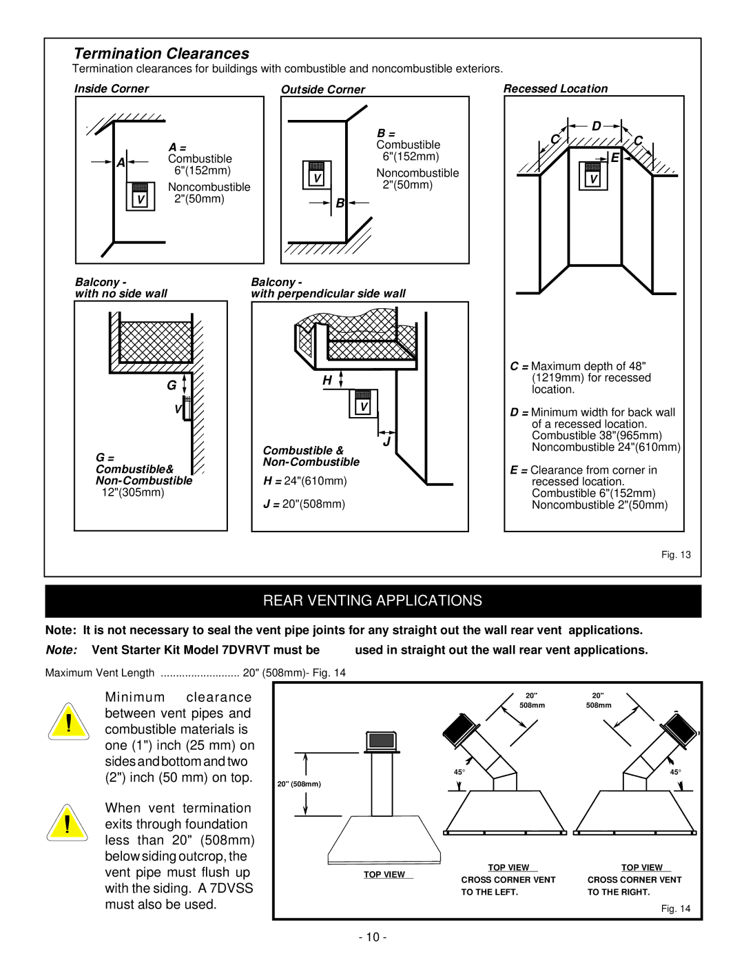
Termination clearances for buildings with combustible and noncombustible exteriors.
Inside Corner
A =
![]() A
A ![]() Combustible 6"(152mm)
Combustible 6"(152mm)
Noncombustible
V2"(50mm)
Outside Corner
B = Combustible
6"(152mm)
VNoncombustible
![]() B
B ![]()
Recessed Location
![]()
![]() D
D ![]()
![]()
CC
![]() E
E ![]()
V
Balcony - | Balcony - |
with no side wall | with perpendicular side wall |
G
V ![]()
![]()
G=
Combustible&
12"(305mm)
H
V
J
Combustible & Non-Combustible
H = 24"(610mm)
J = 20"(508mm)
C = Maximum depth of 48" (1219mm) for recessed location.
D = Minimum width for back wall of a recessed location. Combustible 38"(965mm) Noncombustible 24"(610mm)
E = Clearance from corner in recessed location. Combustible 6"(152mm) Noncombustible 2"(50mm)
Fig. 13
REAR VENTING APPLICATIONS
Note: | It is not necessary to seal the vent pipe joints for any straight out the wall rear vent applications. | ||
Note: | Vent Starter Kit Model 7DVRVT must be | used in straight out the wall rear vent applications. | |
Maximum Vent Length | 20" (508mm)- Fig. 14 |
| |
Minimum clearance between vent pipes and combustible materials is one (1") inch (25 mm) on sides and bottom and two (2") inch (50 mm) on top.
When vent termination exits through foundation less than 20" (508mm) below siding outcrop, the vent pipe must flush up with the siding. A 7DVSS must also be used.
| 20" | 20" | |
| 508mm | 508mm | |
| 45° | 45° | |
20" (508mm) |
|
| |
TOP VIEW | TOP VIEW | TOP VIEW | |
CROSS CORNER VENT | CROSS CORNER VENT | ||
| |||
| TO THE LEFT. | TO THE RIGHT. | |
|
| Fig. 14 | |
- 10 - |
|
|
