VERTICAL SIDEWALL APPLICATIONS
Since it is very important that the venting system maintain its balance between the combustion air intake and the flue gas exhaust, certain limitations as to vent configurations apply and must be strictly adhered to.
The graph showing the relationship between vertical and horizontal side wall venting will help to determine the various vent lengths allowable. Fig. 23.
Minimum clearance between vent pipes and combustible materials is one (1") inch (25
mm)on top, bottom and sides unless otherwise noted.
When vent termination exits through foundation less than 20" below siding outcrop, the vent pipe must flush up with the siding. A 7DVSS must also be used.
It is always best to locate the fireplace in such a way that minimizes the number of offsets and horizontal vent length.
The horizontal vent run refers to the total length of vent pipe from the flue collar of the fireplace to the face of the outer wall.
Horizontal plane means no vertical rise exists on this portion of the vent assembly.
For some installations, it may be desirable to have some amount of the horizontal vent run immediately after the fireplace. A vertical rise must be used but can be located any- where in the vent system, to meet the perim- eters identified in the venting graph.
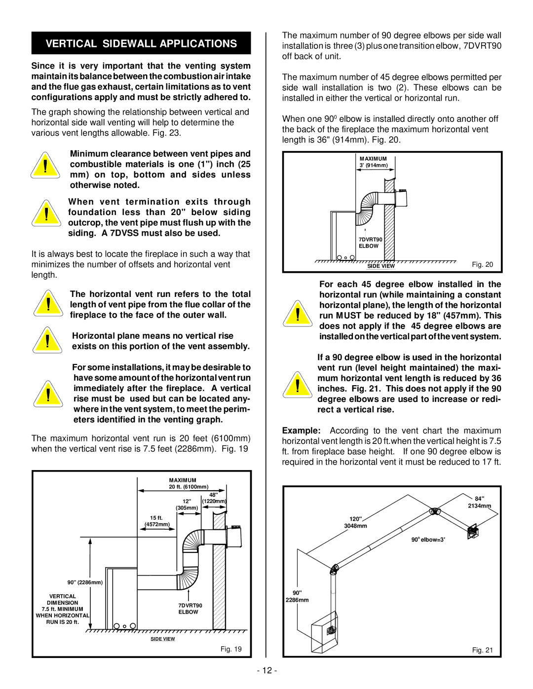
The maximum horizontal vent run is 20 feet (6100mm) when the vertical vent rise is 7.5 feet (2286mm). Fig. 19
| MAXIMUM |
|
| 20 ft. (6100mm) | |
|
| 48" |
| 12" | (1220mm) |
| (305mm) |
|
| 15 ft. |
|
| (4572mm) |
|
90" (2286mm) |
|
|
VERTICAL |
|
|
DIMENSION | 7DVRT90 |
|
7.5 ft. MINIMUM |
| |
ELBOW |
| |
WHEN HORIZONTAL |
| |
|
| |
RUN IS 20 ft. |
|
|
| SIDE VIEW |
|
|
| Fig. 19 |
The maximum number of 90 degree elbows per side wall installation is three (3) plus one transition elbow, 7DVRT90 off back of unit.
The maximum number of 45 degree elbows permitted per side wall installation is two (2). These elbows can be installed in either the vertical or horizontal run.
When one 900 elbow is installed directly onto another off the back of the fireplace the maximum horizontal vent length is 36" (914mm). Fig. 20.
MAXIMUM 3' (914mm)
7DVRT90 |
|
SIDE VIEW | Fig. 20 |
For each 45 degree elbow installed in the horizontal run (while maintaining a constant horizontal plane), the length of the horizontal run MUST be reduced by 18" (457mm). This does not apply if the 45 degree elbows are installed on the vertical part of the vent system.
If a 90 degree elbow is used in the horizontal vent run (level height maintained) the maxi- mum horizontal vent length is reduced by 36 inches. Fig. 21. This does not apply if the 90 degree elbows are used to increase or redi- rect a vertical rise.
Example: According to the vent chart the maximum horizontal vent length is 20 ft.when the vertical height is 7.5 ft. from fireplace base height. If one 90 degree elbow is required in the horizontal vent it must be reduced to 17 ft.
84" |
2134mm |
120" |
3048mm |
90o elbow=3' |
90" |
2286mm |
Fig. 21 |
- 12 -