DVBR Series Direct Vent Gas Fireplace |
|
|
| ||
|
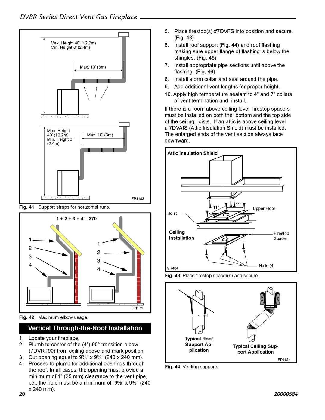
| 5. Place firestop(s) #7DVFS into position and secure. | |||
|
|
| (Fig. 43) |
| |
Max. Height 40’ (12.2m) | 6. | Install roof support (Fig. 44) and roof flashing | |||
Min. Height 8’ (2.4m) | |||||
| making sure upper flange of flashing is below the | ||||
|
|
| |||
|
|
| shingles. (Fig. 46) |
| |
| Max. 10’ (3m) | 7. Install appropriate pipe sections until above the | |||
|
|
| flashing. (Fig. 46) |
| |
|
| 8. Install storm collar and seal around the pipe. | |||
|
| 9. Add additional vent lengths for proper height. | |||
|
| 10. Apply high temperature sealant to 4” and 7” collars | |||
|
|
| of vent termination and | install. | |
|
| If there is a room above ceiling level, firestop spacers | |||
|
| must be installed on both the bottom and the top side | |||
|
| of the ceiling joists. If an attic is above ceiling level | |||
Max. Height |
| a 7DVAIS (Attic Insulation Shield) must be installed. | |||
Max. 10’ (3m) | The enlarged ends of the vent section always face | ||||
40’ (12.2m) | |||||
Min. Height 8’ |
| downward. |
| ||
(2.4m) |
|
|
|
| |
|
| Attic Insulation Shield |
| ||
| FP1183 |
|
|
| |
Fig. 41 Support straps for horizontal runs. |
| 11” | 11” | ||
| Upper Floor | ||||
|
| Joist |
| ||
1 + 2 + 3 + 4 = 270° |
|
|
| ||
|
| Ceiling | Firestop | ||
1 | 1 | Installation | Spacer | ||
|
|
| |||
2 |
|
|
| ||
2 |
|
|
| ||
3 |
|
|
| ||
3 |
|
|
| ||
4 |
|
| Nails (4) | ||
4 | VR404 | ||||
|
| ||||
|
|
| |||
|
| Fig. 43 Place firestop spacer(s) and secure. | |||
FP1179
Fig. 42 Maximum elbow usage.
Vertical Through-the-Roof Installation
1. | Locate your fireplace. |
| Typical Roof |
|
2. | Plumb to center of the (4”) 90° transition elbow |
| Support Ap- | Typical Ceiling Sup- |
| (7DVRT90) from ceiling above and mark position. |
| plication | |
|
| port Application | ||
3. | Cut opening equal to 9³⁄₈" x 9³⁄₈" (240 x 240 mm). |
|
| FP1184 |
4. | Proceed to plumb for additional openings through |
|
| |
Fig. 44 | Venting supports. |
| ||
| the roof. In all cases, the opening must provide a |
| ||
|
|
|
|
minimum of 1” (25 mm) clearance to the vent pipe, i.e., the hole must be a minimum of 9³⁄₈" x 9³⁄₈" (240 x 240 mm).
20 | 20000584 |
