FULL SIZE ELECTRIC CONVECTION OVEN - REMOVAL AND REPLACEMENT OF PARTS
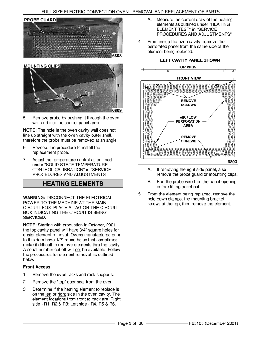
5.Remove probe by pushing it through the oven wall and into the control panel area.
NOTE: The hole in the oven cavity wall does not line up straight with the oven cavity outer shell, therefore the probe must be removed at an angle.
6.Reverse the procedure to install the replacement probe.
7.Adjust the temperature control as outlined under "SOLID STATE TEMPERATURE CONTROL CALIBRATION" in "SERVICE PROCEDURES AND ADJUSTMENTS".
HEATING ELEMENTS
WARNING: DISCONNECT THE ELECTRICAL POWER TO THE MACHINE AT THE MAIN CIRCUIT BOX. PLACE A TAG ON THE CIRCUIT BOX INDICATING THE CIRCUIT IS BEING SERVICED.
NOTE: Starting with production in October, 2001, the top cavity panel will have 3/4" square holes for easier element removal. Ovens manufactured prior to this date have 1/2" round holes that sometimes make it difficult to remove elements thru the cavity. A serial number cut off will not be available. Follow the procedures for element removal as outlined below.
Front Access
1.Remove the oven racks and rack supports.
2.Remove the "top" door seal from the oven.
3.Determine if the heating element to replace is on the left or right side in the oven cavity. The element locations from front to back are: Right side - R1, R2 & R3; Left side - R4, R5 & R6.
A.Measure the current draw of the heating elements as outlined under "HEATING ELEMENT TEST" in "SERVICE PROCEDURES AND ADJUSTMENTS".
4.From inside the oven cavity, remove the perforated panel from the same side of the element being replaced.
A.If removing the right side panel, also remove the probe guard or mounting clips.
B.Run the probe wire thru the panel opening before lifting panel out.
5.From the element being replaced, remove the hold down clamps, the mounting bracket screws at the top, then remove the element.
Page 9 of 60 |
| F25105 (December 2001) |
|
