Manuals
/
Wayne-Dalton
/
Household Appliance
/
Garage Door Opener
Wayne-Dalton
3982 Disconnect Installation, NOTE: It is recommended that 1/4” lag screw loca
Models:
3982
1
14
36
36
Download
36 pages
37.25 Kb
11
12
13
14
15
16
17
18
Troubleshooting
Install
Warranty
Maintenance
Symptom
Jumper Settings: Opener
Safety
power back on at fuse box
service person immediately
Page 14
Image 14
Page 13
Page 15
Page 14
Image 14
Page 13
Page 15
Contents
Important Notice
Model 3982 idrive Extension Spring Kit
FCC and IC Statement
Table of Contents
System Requirements
FCC Regulatory Information
INSTALLATION AND USE
INSTALLATION AND USE
Hardware Kit: 3982 idrive Extension Spring Kit
idrive Package Contents
idrive Hardware Kit
Available Accessories: For idrive
Tools Needed
Step 1: Extension Spring Relief
idrive Retro-fitInstallation
Extension idrive Installation
Step 2: Remove Front Sheave
NOTE: In some instances there
Step 4: Flag Bracket Installation
Step 4A: Track Width Conformation
shown in step
NOTE Do not remove shrink wrap from cable
Step 5: Cable Drum Installation
Step 6 Bottom Bracket Lifting Cables
drums until instructed to do so
wrapped oppositely on the drum
Step 7: Drum Wrap Installation
Step 8 Extension Spring Counterbalance
WARNING TO AVOID SEVERE IN
Step 9: Safety Cable Installation
Step 10 Lower the Door
JURY DO NOT PLACE FINGERS OR HAND
body. Do not hold by the motor
Step 11: idrive Opener/Torque Tube Assembly
NOTE Hold the opener by the main
NOTE: Do not force the opener onto
Step 13: Secure idrive Opener
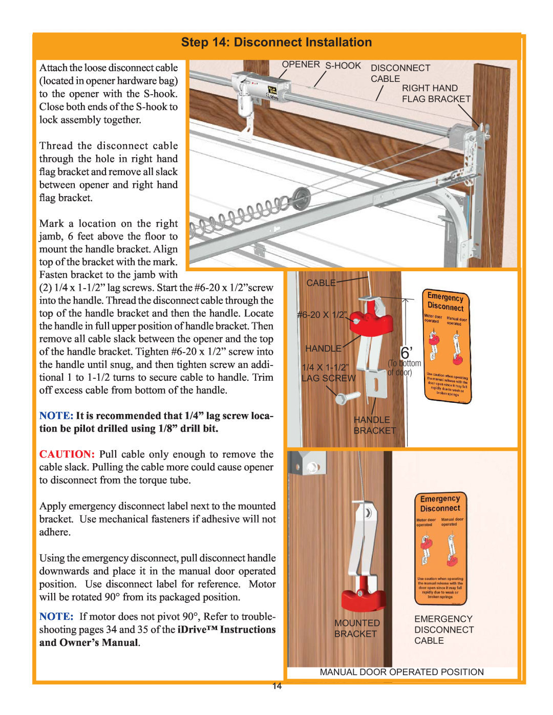
NOTE: It is recommended that 1/4” lag screw loca
Step 14: Disconnect Installation
tion be pilot drilled using 1/8” drill bit
and Owner’s Manual
Pre-OperationInstallation
Step 15: Wall Station Installation
Step 16 Multi-Opener/LightFixture Programming
Switch Settings Light Fixture
Jumper Settings: Opener
Step 17: Light Fixture Installation
CEILING MOUNTING
WALL MOUNTING
Light Fixture Installation Continued
power back on at fuse box
nectors
Step 18: Photoelectric Safety Sensor Installation
NOTE: If wires must be lengthened or spliced into
Photoelectric Safety Sensor
Installation Continued
LIGHT FIXTURE POWER OUTLET RECEPTACLE
Step 19: Power Connection Standard Wiring
CONVENIENT POWER OUTLET
#6 X 7/8 WOOD SCREWS POWER CORD FEMALE END OPENER
Step 20 Power Connection Permanent Wiring Option
Step 22: Photoelectric Safety Sensor Alignment
Step 21 Securing the Opener
Changing the wall station’s security code
Wall Station Programming
UP/DOWN BUTTON PROFILE BUTTON
Step 24 Install Routine
MOTOR OPERATED POSITION
Step 27: Custom Settings
Step 25: Detent Adjustment if required
Step 26: Lock Arm Installation
Step 28 Photoelectric Obstruction Sensor Test
Step 29: Contact Obstruction Test
CHANGING THE TRANSMITTER’S SECURITY CODE
Step 30: Transmitter Security Code
Change and Programming
TRANSMITTER PROGRAMMING
per Step
Teaching Power Unit
Step 31: Programming HomeLink to idrive
PROGRAMMING Training HomeLink Unit
Operation
Important Safety Instructions
8.SAVE THESE INSTRUCTIONS
Transmitter Operation
service person immediately
Wall Station Operation
DISCONNECTED, MOTOR UP POSITION
Manual Door Operation Emergency Disconnect
MOTOR DOWN POSITION DOOR LOCKED
Battery replacement
Maintenance
Monthly Maintenance
NOTE: Dispose of dead batteries properly
PROBABLE CAUSE
Troubleshooting
SYMPTOM
CORRECTIVE ACTION
SYMPTOM
Troubleshooting continued
Lock Arm Troubleshooting
SYMPTOM
Questions??
Wayne-DaltonCustomer Service
LIFETIME LIMITED WARRANTY
For quick answers and helpful advise, call
Top
Page
Image
Contents