Operating Instructions and Parts Manual

JCU50


Maintenance (Cont’d)

NOTE: Once a bladder is leaking or bro- ken, the bladder cannot be repaired. The tank must be replaced.

LUBRICATION

The bearing used in the pumps are life- time lubricated at the factory and require no additional lubrication.

PRECHARGED TANK

Some air is lost through the bladder in any tank. To prevent tank failure, check the tank precharge on a yearly basis.

1.Open a faucet nearest the tank and allow all water to drain from the tank.

2.Measure the tank precharge at the valve stem using a tire gauge.

3.If necessary, adjust the precharge with an air pump 28 - 30 psi on 1/2, 3/4 and 1 HP pumps.

REMOVING OLD SHAFT SEAL

Turn disconnect switch to “off” posi-

tion.

1.Open a faucet nearest the tank and allow all water to drain from the tank.

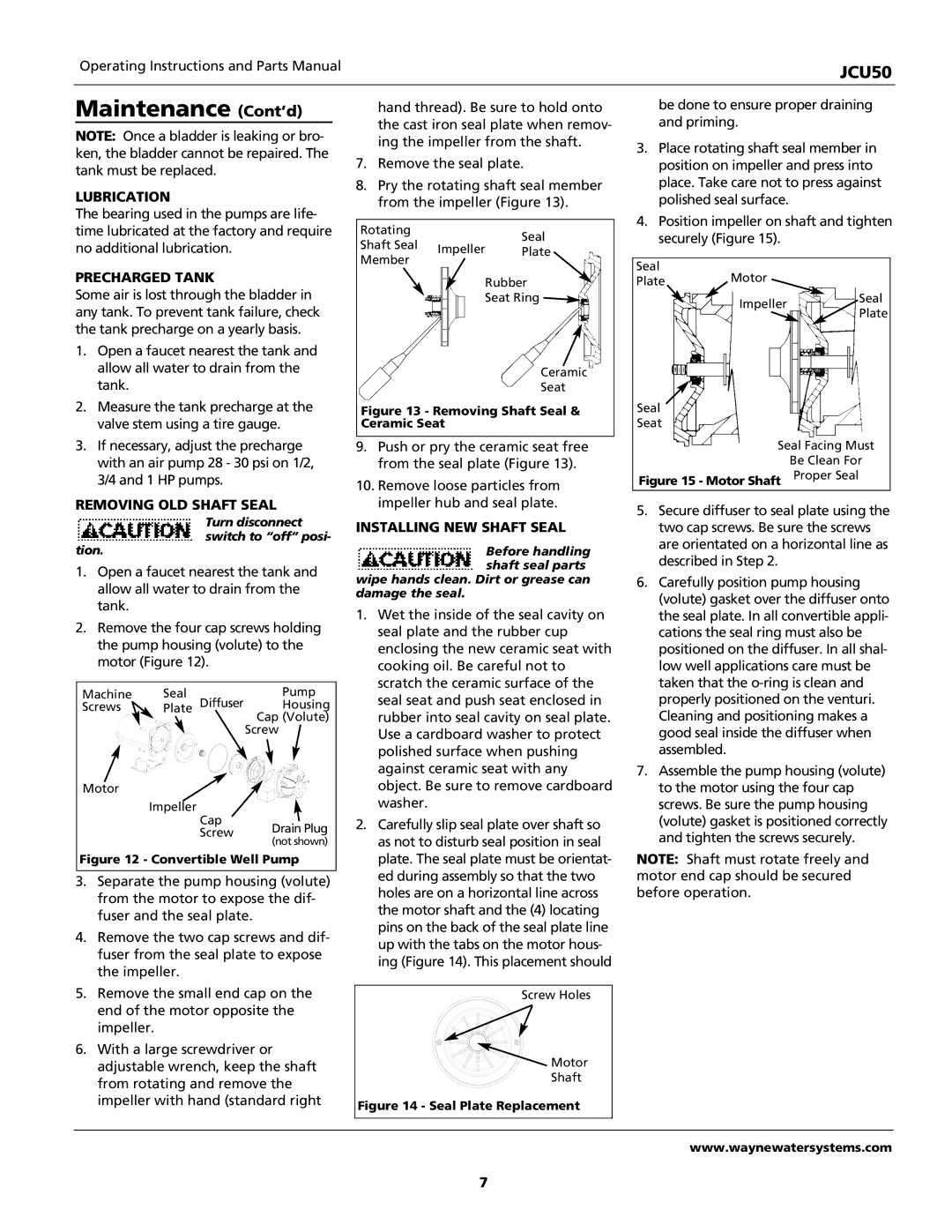
2.Remove the four cap screws holding the pump housing (volute) to the motor (Figure 12).

Machine

Seal

Pump

Screws

Plate Diffuser

Housing


Cap (Volute)


Screw

Motor


Impeller


Cap

Drain Plug


Screw


(not shown)


Figure 12 - Convertible Well Pump

3.Separate the pump housing (volute) from the motor to expose the dif- fuser and the seal plate.

4.Remove the two cap screws and dif- fuser from the seal plate to expose the impeller.

5.Remove the small end cap on the end of the motor opposite the impeller.

6.With a large screwdriver or adjustable wrench, keep the shaft from rotating and remove the impeller with hand (standard right

hand thread). Be sure to hold onto the cast iron seal plate when remov- ing the impeller from the shaft.

7.Remove the seal plate.

8.Pry the rotating shaft seal member from the impeller (Figure 13).

Rotating


Seal

Shaft Seal

Impeller

Plate


Member

Rubber

Seat Ring

Ceramic

Seat

Figure 13 - Removing Shaft Seal & Ceramic Seat

9.Push or pry the ceramic seat free from the seal plate (Figure 13).

10.Remove loose particles from impeller hub and seal plate.

INSTALLING NEW SHAFT SEAL

Before handling shaft seal parts wipe hands clean. Dirt or grease can

damage the seal.

1.Wet the inside of the seal cavity on seal plate and the rubber cup enclosing the new ceramic seat with cooking oil. Be careful not to scratch the ceramic surface of the seal seat and push seat enclosed in rubber into seal cavity on seal plate. Use a cardboard washer to protect polished surface when pushing against ceramic seat with any object. Be sure to remove cardboard washer.

2.Carefully slip seal plate over shaft so as not to disturb seal position in seal plate. The seal plate must be orientat- ed during assembly so that the two holes are on a horizontal line across the motor shaft and the (4) locating pins on the back of the seal plate line up with the tabs on the motor hous- ing (Figure 14). This placement should

Screw Holes

Motor

Shaft

Figure 14 - Seal Plate Replacement

be done to ensure proper draining and priming.

3.Place rotating shaft seal member in position on impeller and press into place. Take care not to press against polished seal surface.

4.Position impeller on shaft and tighten securely (Figure 15).

Seal

Plate Motor

Impeller

Seal

Plate


Seal

Seat

Seal Facing Must

Be Clean For

Figure 15 - Motor Shaft Proper Seal

5.Secure diffuser to seal plate using the two cap screws. Be sure the screws are orientated on a horizontal line as described in Step 2.

6.Carefully position pump housing (volute) gasket over the diffuser onto the seal plate. In all convertible appli- cations the seal ring must also be positioned on the diffuser. In all shal- low well applications care must be taken that the o-ring is clean and properly positioned on the venturi. Cleaning and positioning makes a good seal inside the diffuser when assembled.

7.Assemble the pump housing (volute) to the motor using the four cap screws. Be sure the pump housing (volute) gasket is positioned correctly and tighten the screws securely.

NOTE: Shaft must rotate freely and motor end cap should be secured before operation.

www.waynewatersystems.com

7

Page 7
Image 7
Wayne JCU50 Maintenance Cont’d, Lubrication, Precharged Tank, Removing OLD Shaft Seal, Installing NEW Shaft Seal

JCU50 specifications

The Wayne JCU50 is an innovative fuel dispenser designed to meet the needs of modern fueling operations. As part of Wayne's comprehensive suite of fuel dispensing solutions, the JCU50 stands out due to its advanced features, reliable technology, and user-friendly design.

One of the main features of the Wayne JCU50 is its efficient architecture that allows for high throughput, minimizing wait times for customers. The dispenser is equipped with multiple product fueling capabilities, enabling it to handle various fuel types including gasoline, diesel, and even alternative fuels. This flexibility is crucial for service stations looking to adapt to shifting market demands and the growing popularity of biofuels and electrification.

The JCU50 utilizes smart technology, incorporating digital displays that are user-friendly and intuitive. These displays provide customers with essential information including price per gallon, total sale amount, and promotional messages, enhancing the customer experience. Additionally, the dispenser's interface is designed for easy interaction, reducing confusion at the pump.

Another critical characteristic of the Wayne JCU50 is its robust construction aimed at durability and longevity. The dispenser is designed to withstand harsh weather conditions and heavy usage, ensuring reliable operation across all environments. The materials used in its construction are resistant to corrosion, promoting a longer lifespan and reducing maintenance costs.

In terms of technology, the JCU50 integrates advanced payment solutions, supporting various payment methods such as credit cards, mobile payments, and loyalty programs. This feature not only enhances convenience for customers but also boosts sales opportunities for operators. Furthermore, the dispenser is equipped with state-of-the-art security measures to safeguard transactions and prevent fraudulent activities.

The Wayne JCU50 also emphasizes sustainability. With increasing regulatory pressures around emissions and environmental responsibility, the dispenser supports eco-friendly practices, making it easier for fuel retailers to comply with new regulations.

Overall, the Wayne JCU50 represents a sophisticated solution for fuel dispensers, marrying efficiency with technology and sustainability. Its myriad features and durable design make it an excellent choice for fuel retailers looking to modernize their operations while enhancing customer satisfaction and boosting sales.