NOTE
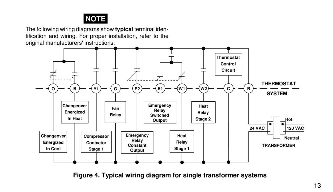
The following wiring diagrams show typical terminal iden- tification and wiring. For proper installation, refer to the original manufacturers' instructions.
O B Y1
Changeover
Energized
In Heat
G
Fan
Relay
E2 E1 W1
Emergency
Relay
Switched
Output
W2
Heat
Relay
Stage 2
Thermostat
Control
Circuit
THERMOSTAT
C R
SYSTEM
Hot
24 VAC | 120 VAC |
Changeover
Energized
In Cool
Compressor
Contactor
Stage 1
Emergency
Relay
Constant
Output
Heat
Relay
Stage 1
Neutral
TRANSFORMER
Figure 4. Typical wiring diagram for single transformer systems
13