MGC Hardware and Installation Manual
Connecting and Setting Up the MGC-100
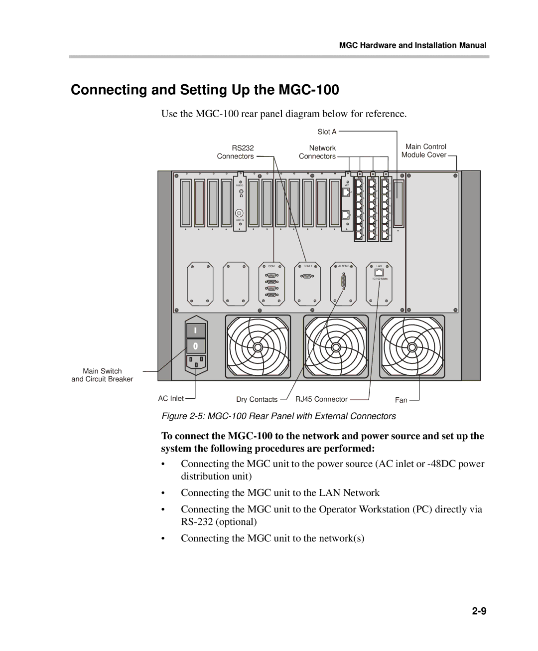
Use the MGC-100 rear panel diagram below for reference.
Main Switch
and Circuit Breaker
Slot A
RS232 | Network |
| Main Control |
Connectors | Connectors |
| Module Cover |
MUSIC |
|
|
|
LINE IN |
|
|
|
COM | COM 1 | ALARMS | LAN |
|
|
| 10/100 Mbits |
AC Inlet |
| Dry Contacts | RJ45 Connector | Fan |
|
Figure 2-5: MGC-100 Rear Panel with External Connectors
To connect the
•Connecting the MGC unit to the power source (AC inlet or
•Connecting the MGC unit to the LAN Network
•Connecting the MGC unit to the Operator Workstation (PC) directly via
•Connecting the MGC unit to the network(s)
