Chapter 3 - System Architecture
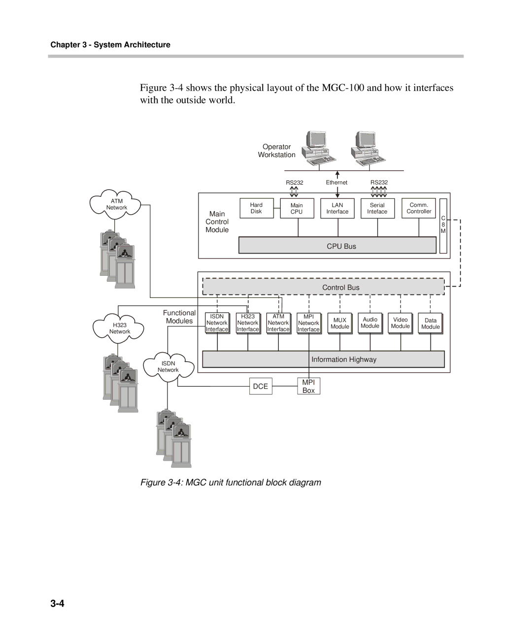
Figure 3-4 shows the physical layout of the MGC-100 and how it interfaces with the outside world.
Operator
Workstation
ATM
Network
|
| RS232 | Ethernet | RS232 |
|
Main | Hard | Main | LAN | Serial | Comm. |
Disk | CPU | Interface | Inteface | Controller | |
Control |
|
|
|
| C |
|
|
|
| 8 | |
Module |
|
|
|
| M |
CPU Bus
Functional
|
|
| Control Bus |
ISDN | H323 | ATM | MPI |
H323
Modules
Network | Network | Network | Network | MUX | Audio | Video | Data |
Module | Module | Module | Module |
Network
ISDN
Network
Interface | Interface | Interface | Interface |
Information Highway
DCE |
| MPI |
| Box | |
|
|