MGC Hardware and Installation Manual
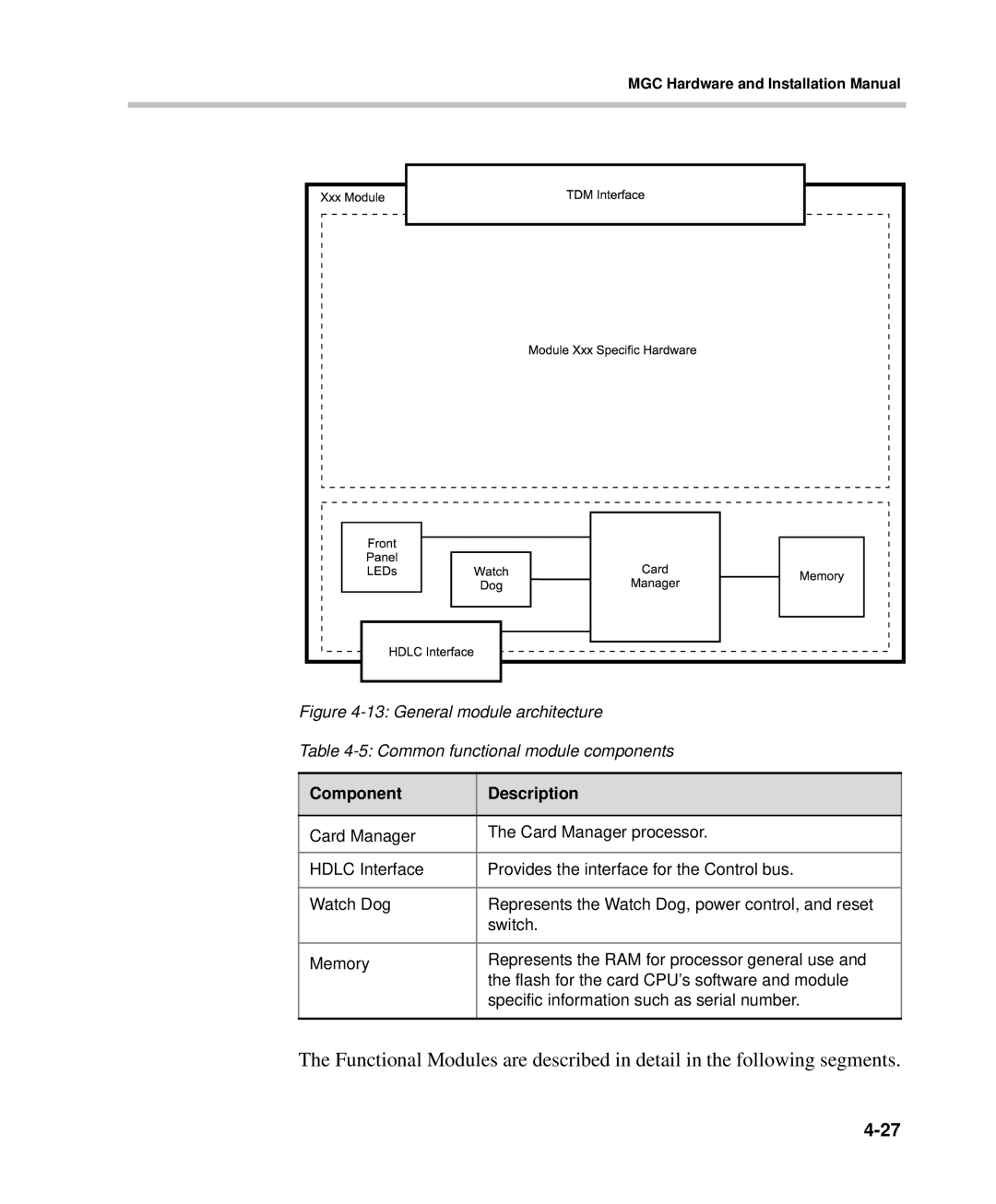
Figure 4-13: General module architecture
Table 4-5: Common functional module components
Component | Description |
|
|
Card Manager | The Card Manager processor. |
|
|
HDLC Interface | Provides the interface for the Control bus. |
|
|
Watch Dog | Represents the Watch Dog, power control, and reset |
| switch. |
|
|
Memory | Represents the RAM for processor general use and |
| the flash for the card CPU’s software and module |
| specific information such as serial number. |
|
|
The Functional Modules are described in detail in the following segments.