MGC Hardware and Installation Manual
MGC-50 Components Location
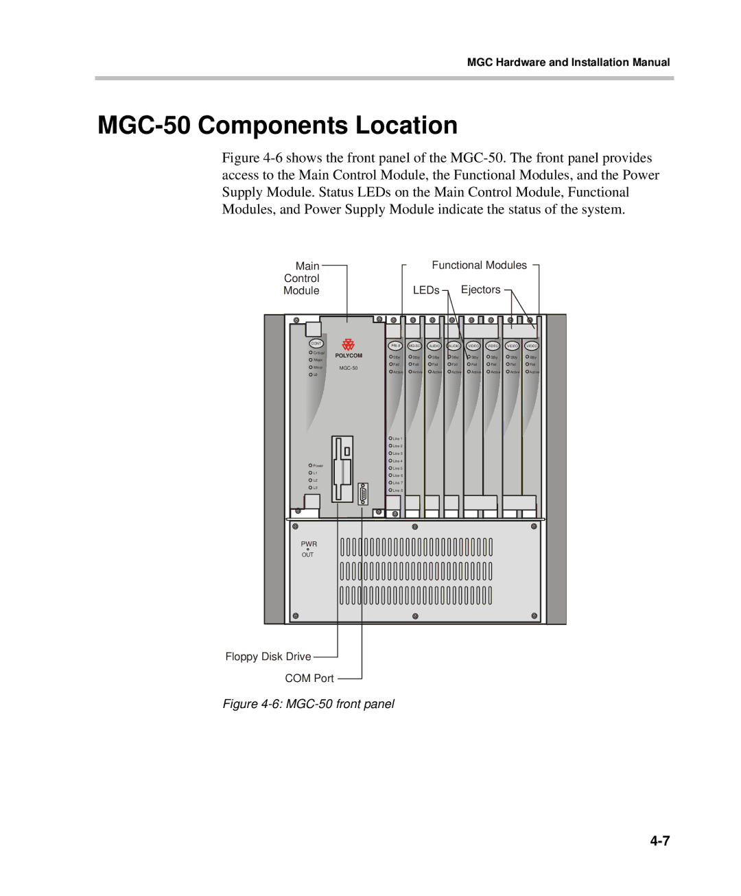
Figure 4-6 shows the front panel of the MGC-50. The front panel provides access to the Main Control Module, the Functional Modules, and the Power Supply Module. Status LEDs on the Main Control Module, Functional Modules, and Power Supply Module indicate the status of the system.
Main |
|
|
| Functional Modules | ||||||
Control |
|
| LEDs | Ejectors |
|
| ||||
Module |
|
|
|
| ||||||
CONT |
| AUDIO | AUDIO | VIDEO | VIDEO | VIDEO | VIDEO | |||
|
| |||||||||
Critical | POLYCOM | Stby | Stby | Stby | Stby | Stby | Stby | Stby | Stby | |
Major | ||||||||||
| Fail | Fail | Fail | Fail | Fail | Fail | Fail | Fail | ||
Minor | ||||||||||
Active | Active | Active | Active | Active | Active | Active | Active | |||
L0 |
| |||||||||
|
|
|
|
|
|
|
|
| ||
|
| Line 1 |
|
|
|
|
|
|
| |
|
| Line 2 |
|
|
|
|
|
|
| |
|
| Line 3 |
|
|
|
|
|
|
| |
|
| Line 4 |
|
|
|
|
|
|
| |
Power |
| Line 5 |
|
|
|
|
|
|
| |
L1 |
|
|
|
|
|
|
|
| ||
| Line 6 |
|
|
|
|
|
|
| ||
|
|
|
|
|
|
|
|
| ||
L2 |
| Line 7 |
|
|
|
|
|
|
| |
|
|
|
|
|
|
|
|
| ||
L3 |
| Line 8 |
|
|
|
|
|
|
| |
|
|
|
|
|
|
|
|
| ||
PWR |
|
|
|
|
|
|
|
|
| |
OUT |
|
|
|
|
|
|
|
|
| |
Floppy Disk Drive |
|
|
|
|
|
|
|
|
| |
COM Port |
|
|
|
|
|
|
|
|
| |
Figure |
|
|
|
|
|
|
| |||