Chapter 2 - Hardware Installation
Connecting and Setting Up the MGC-50
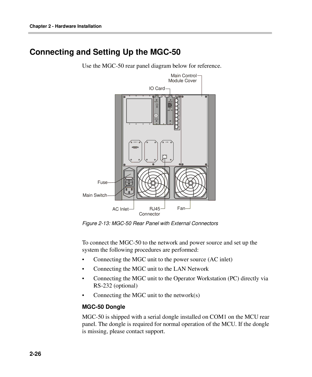
Use the
Main Control
Module Cover
IO Card
COM 1 |
| LAN |
Fuse |
|
|
Main Switch |
|
|
AC Inlet | RJ45 | Fan |
| Connector |
|
Figure 2-13: MGC-50 Rear Panel with External Connectors
To connect the
•Connecting the MGC unit to the power source (AC inlet)
•Connecting the MGC unit to the LAN Network
•Connecting the MGC unit to the Operator Workstation (PC) directly via
•Connecting the MGC unit to the network(s)