MGC Hardware and Installation Manual
Backplane
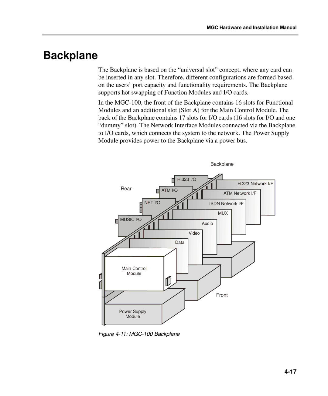
The Backplane is based on the “universal slot” concept, where any card can be inserted in any slot. Therefore, different configurations are formed based on the users’ port capacity and functionality requirements. The Backplane supports hot swapping of Function Modules and I/O cards.
In the
|
|
|
|
|
|
|
|
|
| Backplane |
Rear |
|
|
|
|
| H.323 I/O | H.323 Network I/F | |||
|
|
|
|
| ||||||
|
| ATM I/O | ||||||||
|
| ATM Network I/F | ||||||||
| ||||||||||
|
| NET I/O |
|
|
|
|
| |||
|
|
|
|
|
|
| ISDN Network I/F | |||
|
|
|
|
|
|
| ||||
|
|
|
|
|
|
|
|
|
| MUX |
|
|
|
|
|
|
|
|
|
| |
|
|
|
|
|
|
|
|
|
| |
|
|
|
|
|
|
|
|
|
| |
MUSIC I/O![]()
![]()
Audio
Video
Data
Main Control
Module
Front
Power Supply
Module