MGC Hardware and Installation Manual
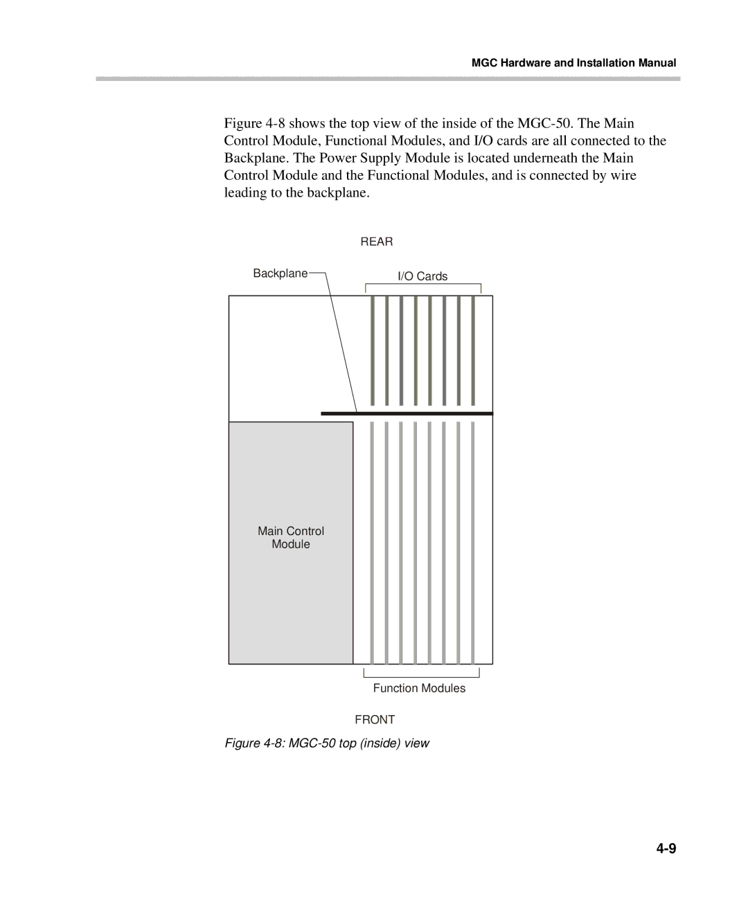
Figure 4-8 shows the top view of the inside of the MGC-50. The Main Control Module, Functional Modules, and I/O cards are all connected to the Backplane. The Power Supply Module is located underneath the Main Control Module and the Functional Modules, and is connected by wire leading to the backplane.
| REAR | |
Backplane |
| I/O Cards |
|
|
|
Main Control
Module
Function Modules
FRONT