MGC Hardware and Installation Manual
Main |
|
|
| Functional Modules | ||||||
Control |
|
| LEDs | Ejectors |
|
| ||||
Module |
|
|
|
| ||||||
CONT |
| AUDIO | AUDIO | VIDEO | VIDEO | VIDEO | VIDEO | |||
|
| |||||||||
Critical | POLYCOM | Stby | Stby | Stby | Stby | Stby | Stby | Stby | Stby | |
Major | ||||||||||
| Fail | Fail | Fail | Fail | Fail | Fail | Fail | Fail | ||
Minor | ||||||||||
Active | Active | Active | Active | Active | Active | Active | Active | |||
L0 |
| |||||||||
|
|
|
|
|
|
|
|
| ||
|
| Line 1 |
|
|
|
|
|
|
| |
|
| Line 2 |
|
|
|
|
|
|
| |
|
| Line 3 |
|
|
|
|
|
|
| |
|
| Line 4 |
|
|
|
|
|
|
| |
Power |
| Line 5 |
|
|
|
|
|
|
| |
L1 |
|
|
|
|
|
|
|
| ||
| Line 6 |
|
|
|
|
|
|
| ||
|
|
|
|
|
|
|
|
| ||
L2 |
| Line 7 |
|
|
|
|
|
|
| |
|
|
|
|
|
|
|
|
| ||
L3 |
| Line 8 |
|
|
|
|
|
|
| |
|
|
|
|
|
|
|
|
| ||
PWR |
|
|
|
|
|
|
|
|
| |
OUT |
|
|
|
|
|
|
|
|
| |
Floppy Disk Drive |
|
|
|
|
|
|
|
|
| |
COM Port |
|
|
|
|
|
|
|
|
| |
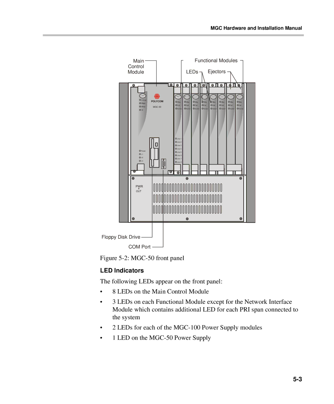
Figure |
|
|
|
|
|
|
| |||
LED Indicators
The following LEDs appear on the front panel:
•8 LEDs on the Main Control Module
•3 LEDs on each Functional Module except for the Network Interface Module which contains additional LED for each PRI span connected to the system
•2 LEDs for each of the
•1 LED on the