MGC Hardware and Installation Manual
Functional Modules
The Functional Modules (cards) perform the various audio, video, and data processing functions for the MGC unit. Both the
The
The
The LED’s on the front of each Functional Module indicate the status of operation and whether it is functioning properly. Functional Modules are installed via the front panel of the MGC unit. A connector at the rear of each function al module connects the module to the backplane. Any module can be inserted into any slot. All Functional Modules are
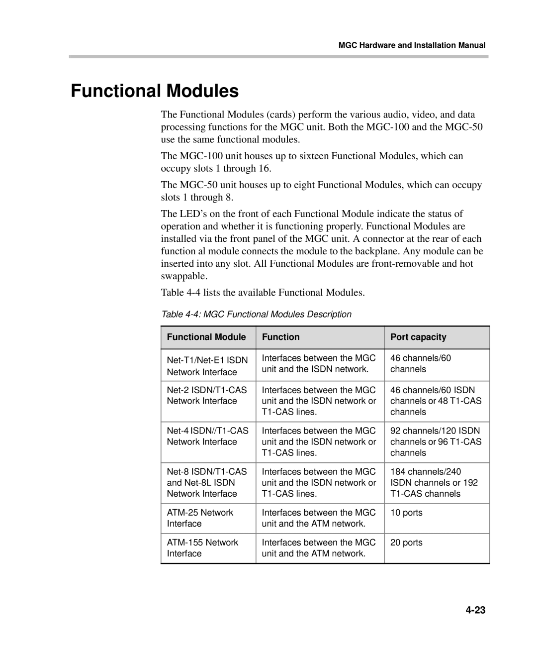
Table
Table
Functional Module | Function | Port capacity |
|
|
|
Interfaces between the MGC | 46 channels/60 | |
Network Interface | unit and the ISDN network. | channels |
|
| |
|
|
|
Interfaces between the MGC | 46 channels/60 ISDN | |
Network Interface | unit and the ISDN network or | channels or 48 |
| channels | |
|
|
|
Interfaces between the MGC | 92 channels/120 ISDN | |
Network Interface | unit and the ISDN network or | channels or 96 |
| channels | |
|
|
|
Interfaces between the MGC | 184 channels/240 | |
and | unit and the ISDN network or | ISDN channels or 192 |
Network Interface | ||
|
|
|
Interfaces between the MGC | 10 ports | |
Interface | unit and the ATM network. |
|
|
|
|
Interfaces between the MGC | 20 ports | |
Interface | unit and the ATM network. |
|
|
|
|
