MGC Hardware and Installation Manual
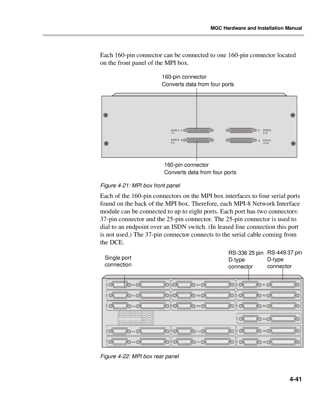
Each 160-pin connector can be connected to one 160-pin connector located on the front panel of the MPI box.
160-pin connector
Converts data from four ports
PORTS A | A | PORTS |
1-4 | | 9-12 |
PORTS B | B | PORTS |
5-8 | | 13-16 |
160-pin connector
Converts data from four ports
Figure 4-21: MPI box front panel
Each of the 160-pin connectors on the MPI box interfaces to four serial ports found on the back of the MPI box. Therefore, each MPI-8 Network Interface module can be connected to up to eight ports. Each port has two connectors: 37-pin connector and the 25-pin connector. The 25-pin connector is used to dial to an endpoint over an ISDN switch. (In leased line connection this port is not used.) The 37-pin connector connects to the serial cable coming from the DCE.
Single port | RS-336 25 pin | RS-449 37 pin |
D-type | D-type |
connection | connector | connector |
DIAL | P12 | DIAL | P7 | DIAL | P1 |
DIAL | P13 | DIAL | P8 | DIAL | P2 |
DIAL | P14 | DIAL | P9 | DIAL | P3 |
P1 | P6 | P11 | | | |
P2 | P7 | P12 | | | |
P3 | P8 | P13 | | DIAL | P4 |
| | P14 | |
P4 | | | |
P9 | P15 | | | |
P5 | P10 | P16 | | | |
DIAL | P15 | DIAL | P10 | DIAL | P5 |
DIAL | P16 | DIAL | P11 | DIAL | P6 |
Figure 4-22: MPI box rear panel