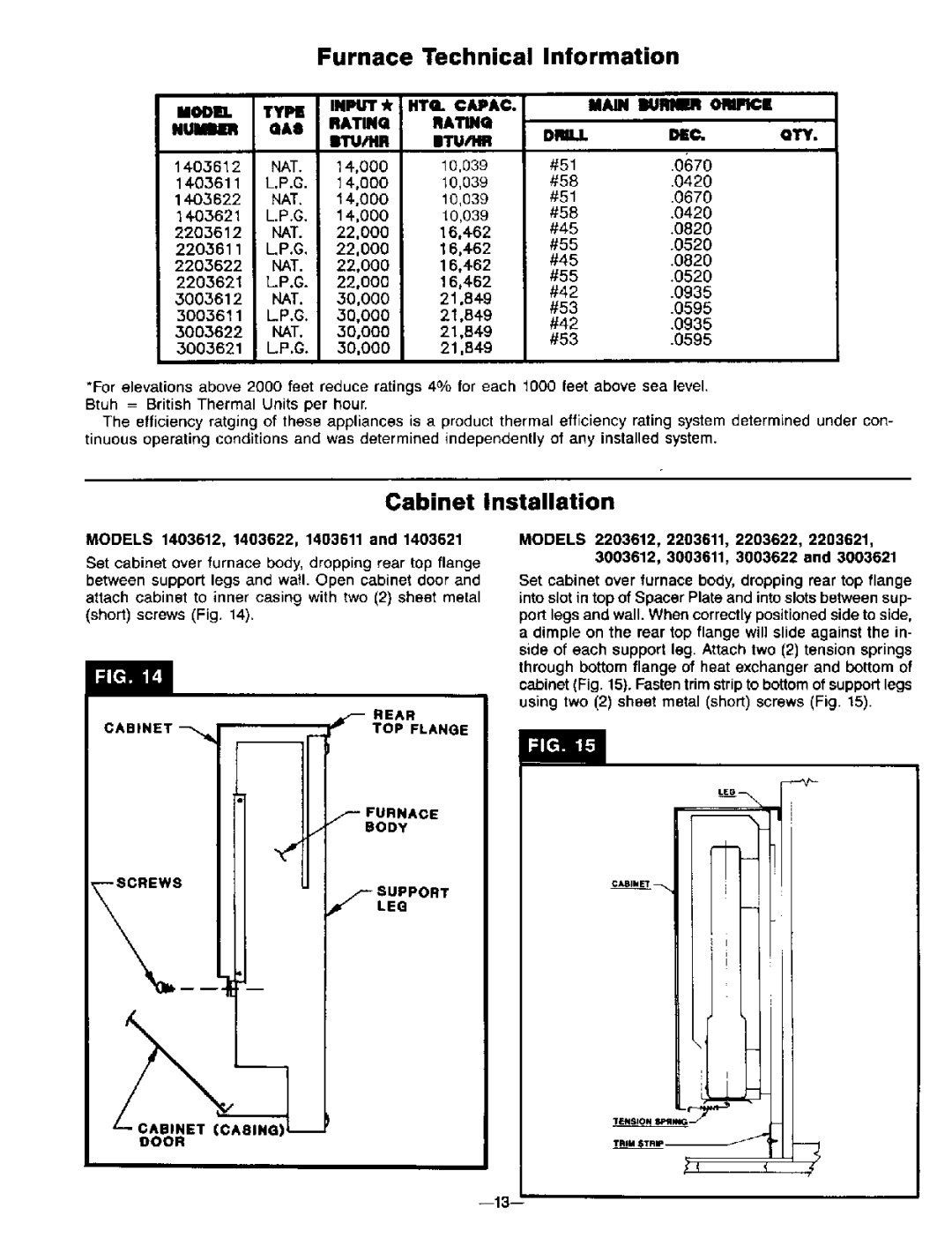
3003612, 3003611, 2203612, 1403612, 2203611 specifications
Williams 2203612, 1403611, 1403612, 3003612, and 2203611 represent a remarkable collection of innovative solutions that cater to diverse needs across various industries. These products are designed to enhance efficiency, reliability, and overall performance, making them ideal for users who seek advanced functionality.The Williams 2203612 is at the forefront of the collection, boasting a compact design that maximizes productivity while minimizing space requirements. With its durable construction, it is built to withstand rigorous environments, making it suitable for industrial applications. Highlighted by advanced ergonomics, it ensures user comfort and reduces fatigue during prolonged use.
Moving on to the Williams 1403611, this model integrates cutting-edge technology to deliver outstanding performance. Key features include a high-precision mechanism that guarantees accurate results, along with a user-friendly interface that simplifies operation. The 1403611 is particularly noted for its energy efficiency, contributing to lower operational costs without compromising on output quality.
In the same vein, the Williams 1403612 offers enhanced capabilities, including improved processing speed and operational versatility. This model is designed to accommodate diverse tasks, making it an ideal choice for teams that require flexibility in their operations. Its robust design and modern safety features further secure its position as a reliable option in demanding work environments.
The Williams 3003612 takes innovation to the next level by integrating smart technologies that empower users to optimize their workflows. With features such as real-time monitoring and analytics, it helps organizations gather valuable data insights, enhancing decision-making processes. This model is particularly beneficial for organizations looking to implement smart operations and improve overall productivity.
Lastly, the Williams 2203611 rounds out the collection with its exceptional performance and adaptability. Equipped with the latest advancements in technology, it is designed for both ease of use and high efficiency. Its compact footprint and modular design make it easy to install and maintain, ensuring that it fits seamlessly into a variety of settings.
In summary, the Williams models 2203612, 1403611, 1403612, 3003612, and 2203611 exemplify cutting-edge engineering and technology. Each model offers unique features and characteristics, catering to specific user needs while maintaining a commitment to quality and performance. Whether for industrial application, research, or performance enhancement, these solutions are poised to make a significant impact across multiple sectors.

