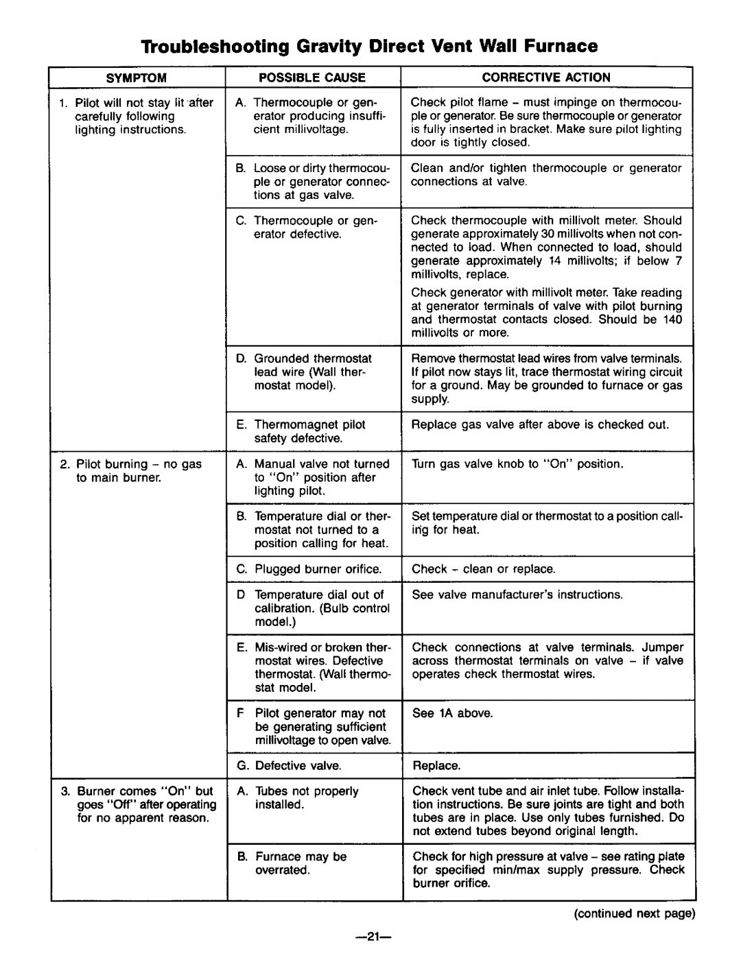
Troubleshooting Gravity Direct Vent Wall Furnace

SYMPTOM

POSSIBLE

CAUSE

1. Pilot will

not stay lit after

A. Thermocouple

or

gen-

carefully

following

erator

producing

insuffi-

lighting

instructions.

cient

millivoltage.


B. Loose or dirtythermocou-


pie or generator connec-


tions

at gas valve.


C. Thermocouple or gen-


erator

defective.


D. Grounded thermostat lead wire (Wall ther- mostat model).

CORRECTIVE ACTION

Check pilot flame - must impinge on thermocou- pie or generator. Be sure thermocouple or generator is fully inserted in bracket. Make sure pilot lighting door is tightly closed.

Clean and/or tighten thermocouple or generator connections at valve.

Check thermocouple with millivolt meter. Should generate approximately 30 millivolts when not con- nected to load. When connected to load, should

generate approximately 14 millivolts; if below 7 millivolts, replace.

Check generator with millivolt meter. Take reading at generator terminals of valve with pilot burning and thermostat contacts closed. Should be 140 millivolts or more.

Remove thermostat lead wires from valve terminals. If pilot now stays lit, trace thermostat wiring circuit for a ground. May be grounded to furnace or gas supply.

2.Pilot burning - no gas to main burner.

3.Burner comes "On" but goes "Off" after operating for no apparent reason.

E. Thermomagnet pilot safety defective.

A.Manual valve not turned to "On" position after lighting pilot.

B.Temperature dial or ther- mostat not turned to a position calling for heat.

C.Plugged burner orifice.

DTemperature dial out of

calibration. (Bulb control model.)

E.Mis-wired or broken ther- mostat wires. Defective

thermostat. 0Nail thermo- stat model.

FPilot generator may not be generating sufficient millivoltage to open valve.

G. Defective valve.

A. Tubes not properly installed.

B. Furnace may be overrated.

g21--

Replace gas valve after above is checked out.

Turn gas valve knob to "On" position.

Set temperature dial or thermostat to a position call- irtg for heat.

Check - clean or replace.

See valve manufacturer's instructions.

Check connections at valve terminals. Jumper across thermostat terminals on valve - if valve

operates check thermostat wires.

See 1A above.

Replace.

Check vent tube and air inlet tube. Follow installa- tion instructions. Be sure joints are tight and both tubes are in place. Use only tubes furnished. Do not extend tubes beyond original length.

Check for high pressure at valve - see rating plate for specified minimax supply pressure. Check burner orifice.

(continued next page)

Page 21
Image 21
Williams 3003611, 3003612 Troubleshooting Gravity Direct Vent Wall Furnace, Symptom Possible Cause, Not stay lit after

3003612, 3003611, 2203612, 1403612, 2203611 specifications

Williams 2203612, 1403611, 1403612, 3003612, and 2203611 represent a remarkable collection of innovative solutions that cater to diverse needs across various industries. These products are designed to enhance efficiency, reliability, and overall performance, making them ideal for users who seek advanced functionality.

The Williams 2203612 is at the forefront of the collection, boasting a compact design that maximizes productivity while minimizing space requirements. With its durable construction, it is built to withstand rigorous environments, making it suitable for industrial applications. Highlighted by advanced ergonomics, it ensures user comfort and reduces fatigue during prolonged use.

Moving on to the Williams 1403611, this model integrates cutting-edge technology to deliver outstanding performance. Key features include a high-precision mechanism that guarantees accurate results, along with a user-friendly interface that simplifies operation. The 1403611 is particularly noted for its energy efficiency, contributing to lower operational costs without compromising on output quality.

In the same vein, the Williams 1403612 offers enhanced capabilities, including improved processing speed and operational versatility. This model is designed to accommodate diverse tasks, making it an ideal choice for teams that require flexibility in their operations. Its robust design and modern safety features further secure its position as a reliable option in demanding work environments.

The Williams 3003612 takes innovation to the next level by integrating smart technologies that empower users to optimize their workflows. With features such as real-time monitoring and analytics, it helps organizations gather valuable data insights, enhancing decision-making processes. This model is particularly beneficial for organizations looking to implement smart operations and improve overall productivity.

Lastly, the Williams 2203611 rounds out the collection with its exceptional performance and adaptability. Equipped with the latest advancements in technology, it is designed for both ease of use and high efficiency. Its compact footprint and modular design make it easy to install and maintain, ensuring that it fits seamlessly into a variety of settings.

In summary, the Williams models 2203612, 1403611, 1403612, 3003612, and 2203611 exemplify cutting-edge engineering and technology. Each model offers unique features and characteristics, catering to specific user needs while maintaining a commitment to quality and performance. Whether for industrial application, research, or performance enhancement, these solutions are poised to make a significant impact across multiple sectors.