ASSEMBLY INSTRUCTIONS
DEALER SET-UP INSTRUCTIONS
Assembly of this cutter is the responsibility of the WOODS dealer. It should be delivered to the owner completely assembled, lubricated and adjusted for nor- mal cutting conditions.
The cutter is shipped partially assembled. Assembly will be easier if components are aligned and loosely assembled before tightening hardware. Recommended torque values for hardware are located on page 72.
Select a suitable working area. A smooth hard surface, such as concrete, will make assembly much quicker. Open parts boxes and lay out parts and hardware to make location easy. Refer to illustrations, accompany- ing text, parts lists and exploded view drawings.
Complete the check list on page 44 when assembly is complete and cutter is delivered to the customer.
Before working underneath, carefully read Oper- ator’s Manual instructions, disconnect driveline, raise mower, securely block up all corners with jackstands, and check stability. Secure blocking prevents equipment from dropping due to hydrau- lic leak down, hydraulic system failures, or mechanical component failures.
Do not disconnect hydraulic lines until machine is securely blocked or placed in lowest position and system pressure is released by operating valve levers.
![]() CAUTION
CAUTION
Always wear relatively tight and belted clothing to avoid entanglement in moving parts. Wear sturdy,
CENTER SECTION ASSEMBLY
Install Hydraulic Hoses
1.Insert one 264 inch (wing cylinder) hose and one 230 inch (center cylinder) hose into the right tube in the center section. Insert one 264 inch hose into the left tube.
2.Extend the 264" hoses approximately 52 inches past the back of the center section. Extend the 230" hose approximately 22 inches past the back of the center section.
3.Secure hose to center section using hose clamps (12), carriage bolts (59) and lock nuts (32). Clamps are used at the both front and at the rear of the deck.
4.Do not tighten clamps at this time. Hoses lengths may need to be adjusted once assembly is complete.
12. Feedline clamp
32. 5/16 NC Lock nut
59.5/16 NC x 1 HHCS GR5 ![]()
![]() 12
12
59
32
DP3
Figure 21. Hoses Clamped to Deck, Rear Right Side
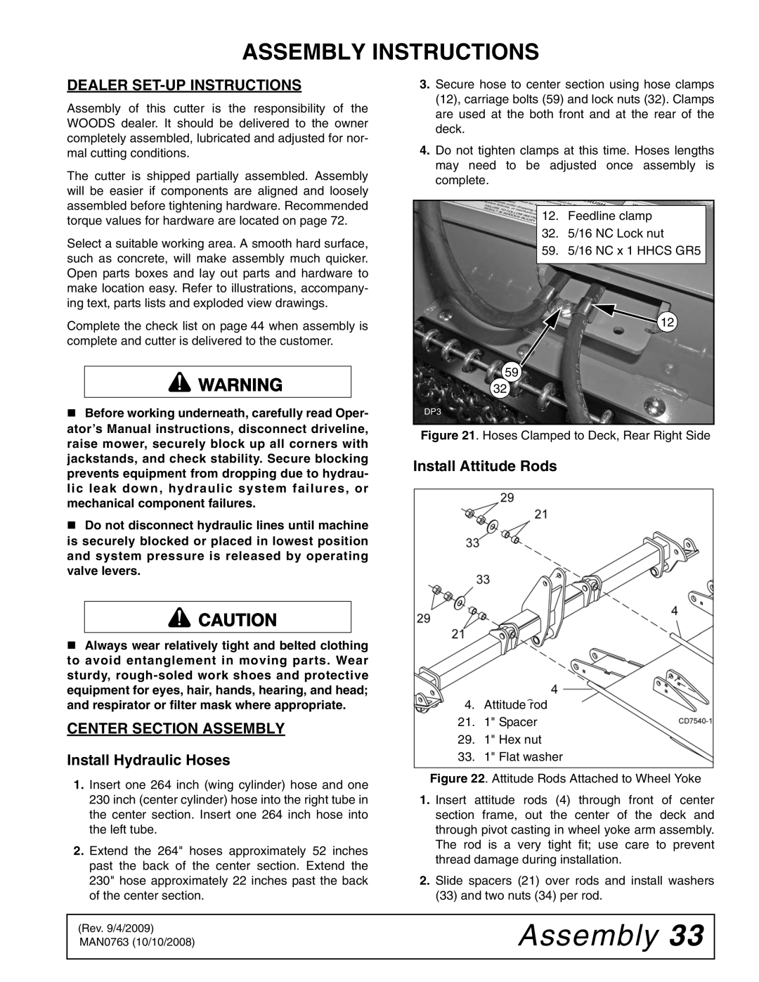
Install Attitude Rods
4. Attitude rod
21. 1" Spacer
29. 1" Hex nut
33. 1" Flat washer
Figure 22. Attitude Rods Attached to Wheel Yoke
1.Insert attitude rods (4) through front of center section frame, out the center of the deck and through pivot casting in wheel yoke arm assembly. The rod is a very tight fit; use care to prevent thread damage during installation.
2.Slide spacers (21) over rods and install washers (33) and two nuts (34) per rod.
(Rev. 9/4/2009) MAN0763 (10/10/2008)