3.Tighten nuts until there is approximately 1 inches of thread exposed past the nuts. Further adjustment will be needed once cutter is attached to tractor drawbar. See Cutting Height Adjustment, page 15.
Install Height Adjustment Cylinder
Refer to Figure 23.
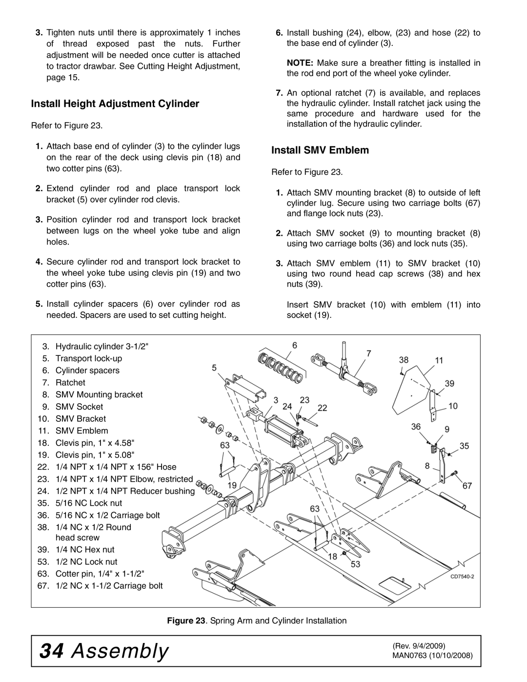
1.Attach base end of cylinder (3) to the cylinder lugs on the rear of the deck using clevis pin (18) and two cotter pins (63).
2.Extend cylinder rod and place transport lock bracket (5) over cylinder rod clevis.
3.Position cylinder rod and transport lock bracket between lugs on the wheel yoke tube and align holes.
4.Secure cylinder rod and transport lock bracket to the wheel yoke tube using clevis pin (19) and two cotter pins (63).
5.Install cylinder spacers (6) over cylinder rod as needed. Spacers are used to set cutting height.
6.Install bushing (24), elbow, (23) and hose (22) to the base end of cylinder (3).
NOTE: Make sure a breather fitting is installed in the rod end port of the wheel yoke cylinder.
7.An optional ratchet (7) is available, and replaces the hydraulic cylinder. Install ratchet jack using the same procedure and hardware used for the installation of the hydraulic cylinder.
Install SMV Emblem
Refer to Figure 23.
1.Attach SMV mounting bracket (8) to outside of left cylinder lug. Secure using two carriage bolts (67) and flange lock nuts (23).
2.Attach SMV socket (9) to mounting bracket (8) using two carriage bolts (36) and lock nuts (35).
3.Attach SMV emblem (11) to SMV bracket (10) using two round head cap screws (38) and hex nuts (39).
Insert SMV bracket (10) with emblem (11) into socket (19).
3. Hydraulic cylinder
5.Transport
6.Cylinder spacers
7.Ratchet
8.SMV Mounting bracket
9.SMV Socket
10.SMV Bracket
11.SMV Emblem
18.Clevis pin, 1" x 4.58"
19.Clevis pin, 1" x 5.08"
22.1/4 NPT x 1/4 NPT x 156" Hose
23.1/4 NPT x 1/4 NPT Elbow, restricted
24.1/2 NPT x 1/4 NPT Reducer bushing
35.5/16 NC Lock nut
36.5/16 NC x 1/2 Carriage bolt
38.1/4 NC x 1/2 Round head screw
39.1/4 NC Hex nut
53. 1/2 NC Lock nut
63. Cotter pin, 1/4" x
67. 1/2 NC x
Figure 23. Spring Arm and Cylinder Installation
34Assembly
(Rev. 9/4/2009) MAN0763 (10/10/2008)