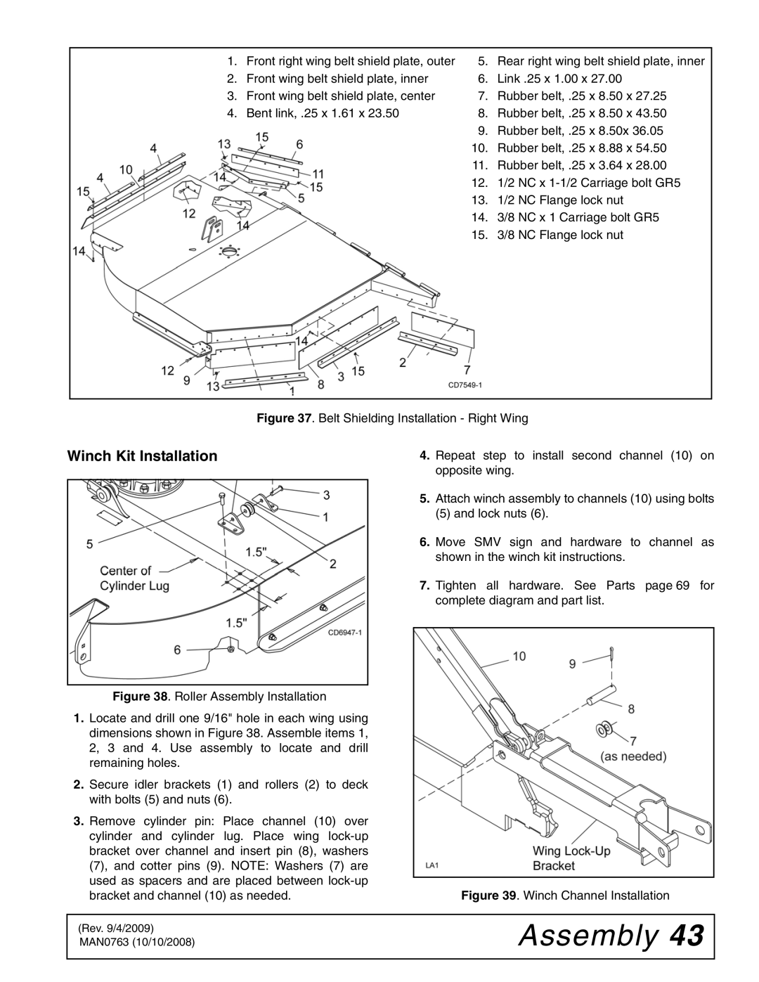
1. | Front right wing belt shield plate, outer | 5. | Rear right wing belt shield plate, inner |
2. | Front wing belt shield plate, inner | 6. | Link .25 x 1.00 x 27.00 |
3. | Front wing belt shield plate, center | 7. | Rubber belt, .25 x 8.50 x 27.25 |
4. | Bent link, .25 x 1.61 x 23.50 | 8. | Rubber belt, .25 x 8.50 x 43.50 |
|
| 9. | Rubber belt, .25 x 8.50x 36.05 |
|
| 10. | Rubber belt, .25 x 8.88 x 54.50 |
|
| 11. | Rubber belt, .25 x 3.64 x 28.00 |
|
| 12. | 1/2 NC x |
|
| 13. | 1/2 NC Flange lock nut |
|
| 14. | 3/8 NC x 1 Carriage bolt GR5 |
|
| 15. | 3/8 NC Flange lock nut |
Figure 37. Belt Shielding Installation - Right Wing
Winch Kit Installation
Figure 38. Roller Assembly Installation
1.Locate and drill one 9/16" hole in each wing using dimensions shown in Figure 38. Assemble items 1, 2, 3 and 4. Use assembly to locate and drill remaining holes.
2.Secure idler brackets (1) and rollers (2) to deck with bolts (5) and nuts (6).
3.Remove cylinder pin: Place channel (10) over cylinder and cylinder lug. Place wing lock-up bracket over channel and insert pin (8), washers (7), and cotter pins (9). NOTE: Washers (7) are used as spacers and are placed between lock-up bracket and channel (10) as needed.
4.Repeat step to install second channel (10) on opposite wing.
5.Attach winch assembly to channels (10) using bolts
(5) and lock nuts (6).
6.Move SMV sign and hardware to channel as shown in the winch kit instructions.
7.Tighten all hardware. See Parts page 69 for complete diagram and part list.
Figure 39. Winch Channel Installation
(Rev. 9/4/2009) MAN0763 (10/10/2008)