Install CV Drive (Optional)
Before installing cutter input driveline to gearbox, check the tag wired to the driveline and the tag wired to the input shaft of gearbox. Ensure the tag rpm speeds match the rpm speed decal on front of cutter. After con- firming all speeds match, remove and discard tags and then complete driveline assembly.
1.Align hole in drive yoke with groove on gearbox input shaft and slide rear half of drive (23) onto shaft.
2.Secure with bolt and nut supplied with drive.
21. CV Drive
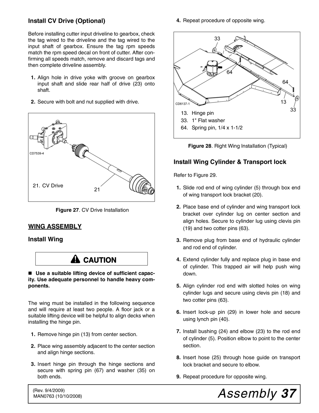
4.Repeat procedure of opposite wing.
13. | Hinge pin |
33. | 1" Flat washer |
64. | Spring pin, 1/4 x |
Figure 28. Right Wing Installation (Typical)
Install Wing Cylinder & Transport lock
Refer to Figure 29.
1.Slide rod end of wing cylinder (5) through box end of wing transport lock bracket (20).
Figure 27. CV Drive Installation
WING ASSEMBLY
Install Wing
![]() CAUTION
CAUTION
Use a suitable lifting device of sufficient capac- ity. Use adequate personnel to handle heavy com- ponents.
The wing must be installed in the following sequence and will require at least two people. A floor jack or a suitable lifting device will be helpful to align decks when installing the hinge pin.
1.Remove hinge pin (13) from center section.
2.Place wing assembly adjacent to the center section and align hinge sections.
3.Insert hinge pin through the hinge sections and secure with spring pin (67) and washer (35) on both ends.
2.Place base end of cylinder and wing transport lock bracket over cylinder lug on center section and align holes. Secure to cylinder lug using clevis pin (19) and two cotter pins (63).
3.Remove plug from base end of hydraulic cylinder and rod end of cylinder.
4.Extend cylinder fully and replace plug in base end of cylinder. This trapped air will help push wing down.
5.Align cylinder rod end with slotted holes on wing cylinder lugs and secure using clevis pin (18) and two cotter pins (63).
6.Insert
7.Install bushing (24) and elbow (23) to the rod end of cylinder (5). Position elbow to point to the center section.
8.Insert hose (25) through hose guide on transport lock bracket and secure to elbow.
9.Repeat procedure for opposite wing.
(Rev. 9/4/2009) MAN0763 (10/10/2008)