4.Place universal cross in vise as shown in Figure 19 and tap on yoke to remove cup. Repeat Step 3 for final removal. Drive remaining cup out with a drift and hammer.
Figure 19
U-Joint Assembly
1.Place seals securely on bearing cups. Insert cup into yoke from outside and press in with hand pressure as far as possible. Insert journal cross into bearing cup with grease fitting away from shaft. Be careful not to disturb needle bearings. Insert another bearing cup directly across from first cup and press in as far as possible with hand pressure.
2.Trap cups in vise and apply pressure. Be sure journal cross is started into bearings and continue pressure with vise, squeezing in as far as possible. Tapping the yoke will help.
3.Seat cups by placing a drift or socket (slightly smaller than the cup) on cup and rap with a hammer. Install snap ring and repeat on opposite cup.
4.Repeat Step 1 and Step 2 to install remaining cups in remaining yoke.
5.Move both yokes in all directions to check for free movement. If movement is restricted, rap on yokes sharply with a hammer to relieve any tension. Repeat until both yokes move in all directions without restriction.
SERVICE TIRES SAFELY
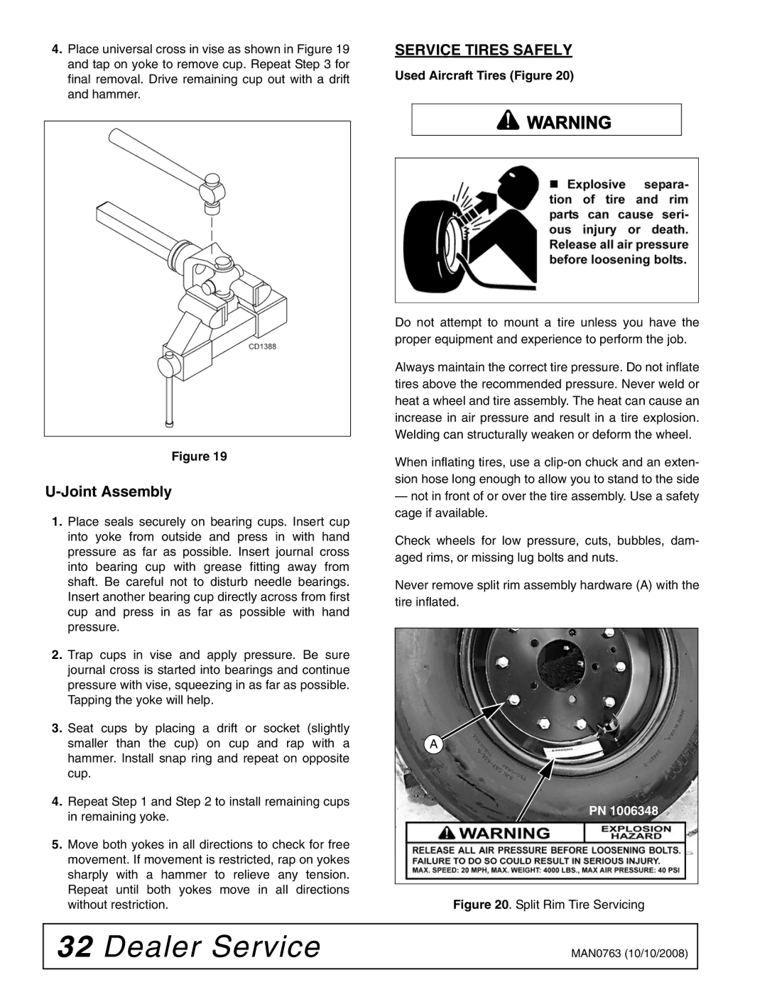
Used Aircraft Tires (Figure 20)
![]() WARNING
WARNING
Do not attempt to mount a tire unless you have the proper equipment and experience to perform the job.
Always maintain the correct tire pressure. Do not inflate tires above the recommended pressure. Never weld or heat a wheel and tire assembly. The heat can cause an increase in air pressure and result in a tire explosion. Welding can structurally weaken or deform the wheel.
When inflating tires, use a
—not in front of or over the tire assembly. Use a safety cage if available.
Check wheels for low pressure, cuts, bubbles, dam- aged rims, or missing lug bolts and nuts.
Never remove split rim assembly hardware (A) with the tire inflated.
![]() A
A
PN 1006348
Figure 20. Split Rim Tire Servicing
32 Dealer Service | MAN0763 (10/10/2008) |
|
|